10.14
SEL-587Z Instruction Manual Date Code 20020903
Testing and Troubleshooting
Acceptance Testing
appropriate element asserts (i.e., 87A1), causing the LED to
illuminate (i.e., top row, first from the left; See Table 10 .4).
Note the magnitude of the voltage applied. It should equal the
87A1 element setting ±5% of the setting and ±4 V.
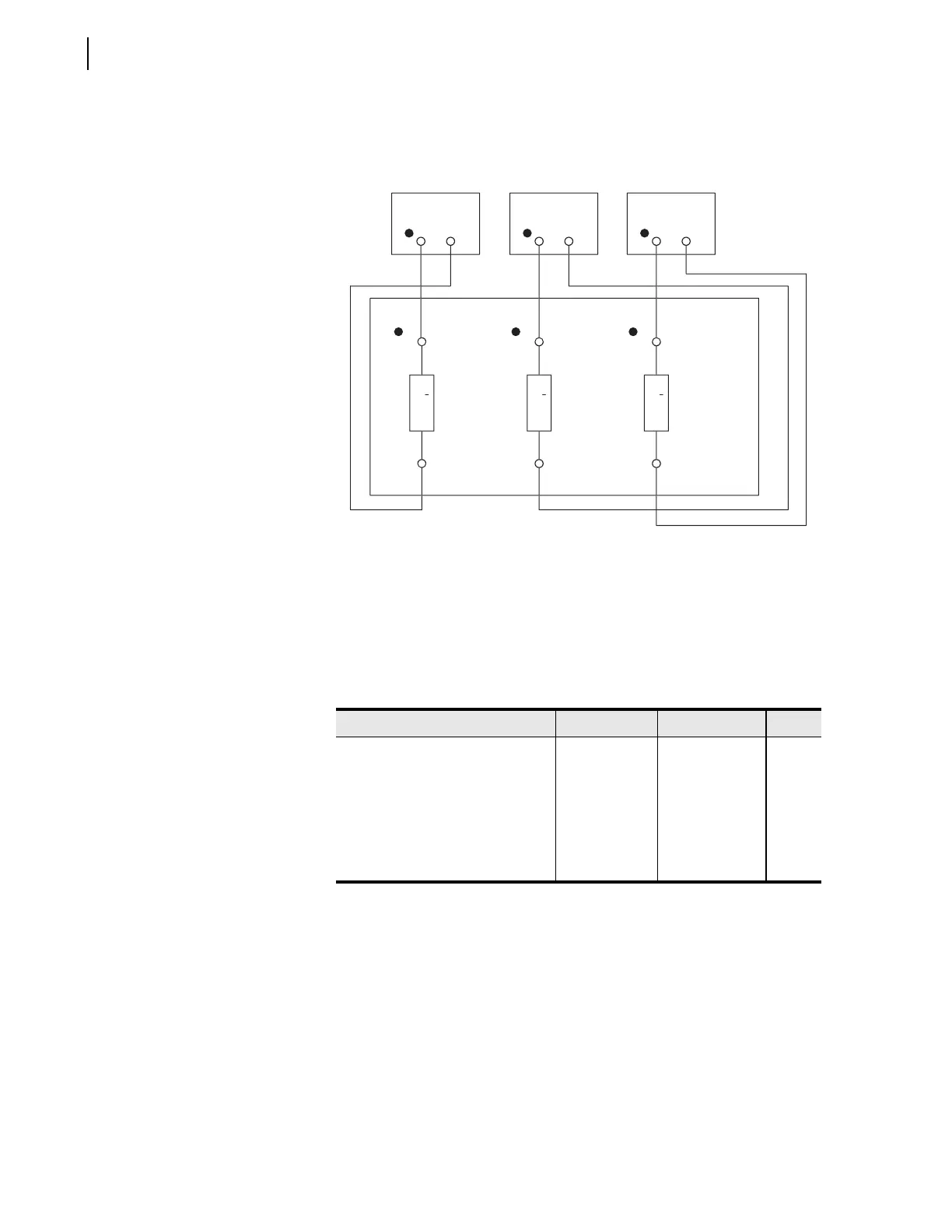
Figure 10.7 Test Connections for Three-Phase Voltage Sources.
Repeat Steps 1 through 3 for each voltage element listed in
Tab le 10 .4 . Remember to view the element with the TAR
command (See Tabl e 10.4). The computer terminal will display
the LED labels from left to right when the TAR command is
issued.
Table 10.4 Instantaneous Overcurrent Elements
and Corresponding Settings/Relay Word Bits/TAR Commands
Element Pickup Setting Relay Word Bit TAR
Differential Element A-Phase Level 1 87A1P 87A1 5
Differential Element A-Phase Level 2 87A2P 87A2 5
Differential Element B-Phase Level 1 87B1P 87B1 5
Differential Element B-Phase Level 2 87B2P 87B2 5
Differential Element C-Phase Level 1 87C1P 87C1 5
Differential Element C-Phase Level 2 87C2P 87C2 5
1
7
7
7
EL-
7
(
artial
Volta
r
Volta
r
Volta
r
10
10
1
1
10


 To Next Page