4.21
Date Code 20020903 SEL-587Z Instruction Manual
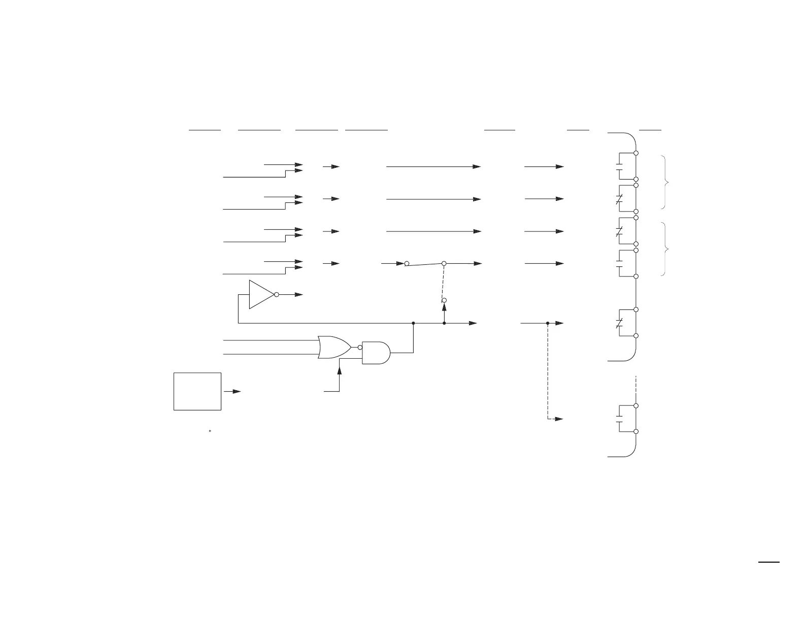
Control Logic
Output Contacts
Figure 4.9 Logic Flow for Example Output Contact Operation.
See Figure 2.7 on page 2.10 in Section 2: Installation and Table 2.2 on
page 2.10 in Section 2: Installation for more information on jumper JMP13.
LAR
T4
T
T2
T1
ner
ized
e-energized
ner
ized
e-ener
ized
en
l
l
en
e-ener
ized, etc.)
en (re
ay fai
e
,
losed (rela
OK)
r
n
rmin
l
ut
ut
ner
ize
e-ener
ized
r
LAR
ogical 0
o
ical 1
o
ical 0
o
ical 1
T
T4
T1
T2
T4
T
T2
T1
L
E
T1
L
E
T2
L
E
T
L
E
T4
ULSE ALAR
LAR
L
E command is also available via the front
anel (CNTRL
ushbutton,
out
ut contact testin
" o
tion). Execution of the
L
E
mm
n
r
l
n a lo
ical 1 in
ut into the above lo
ic.
re
ular out
ut contact OUT4 (JMP13 in
osition YOUT2)
ain board
um
er JMP13 allows out
ut contact OUT4 to o
erate as:
an extra Alarm out
ut contact (JMP13 in
osition ALARM
o
ica
1 (re
ay OK)
r
o
ical 0 (relay failed)
YOUT2
ALARM
P13**
ela
Enters
L
v
l 2
ontact
a
ontact
b
ontact
b
ontact
a
Serial
P
r
mm
n
*
SELOGIC
ontrol E
uation
ettin
s*
ut
ut
n
Example
ela
Word Bit
ela
Word
i
Output
n
il
l
rm
o
ic/Circuitry
en (relay OK)
losed (rela
failed,
r
e-ener
ized, etc.)