Section 04 ENGINE (2-STROKE)
Subsection 06 (BOTTOM END)
04-06-16 SMR2003-011_04_06A.FM
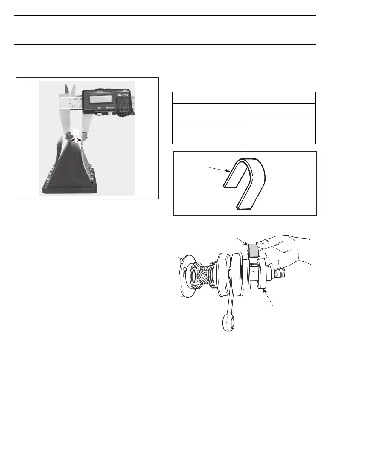
Check stopper distance from center of reed valve
block.
A. 13 ± 0.25 mm (.512 ± .010 in)
NOTE: Distance should be the same on both sides.
Bent stopper as required to obtain the proper dis-
tance.
Air Compressor
Refer to ENGINE MANAGEMENT for compo-
nents inspection. However, if you find aluminum
dust or debris in this area, they may have flowed
toward the injection oil reservoir. In this case, the
oil reservoir and lines must be flushed and the fil-
ter replaced.
CAUTION: Failure to properly clean the oil sys-
tem will result in serious engine damage.
ASSEMBLY
Assembly is essentially the reverse of disassem-
bly procedures. However pay particular attention
to the following.
NOTE: It is recommended to spray BOMBARDIER-
ROTAX injection oil on all moving parts when re-
assembling the engine.
Crankshaft and Bearing
Apply Loctite 767 anti-seize on part of crankshaft
where bearing fits.
Prior to installation, place bearings no. 4 into a
container filled with oil, previously heated to 75°C
(167°F). This will expand bearing and ease instal-
lation.
To properly position the outer bearing(s), a dis-
tance gauge must be temporarily installed against
the inner bearing. Slide the outer bearing until
stopped by the distance gauge, then remove it.
1. Distance gauge
TYPICAL
1. Distance gauge
2. Outer bearing
Distance Ring
When installing the distance ring no. 12, make
sure to position it with its chamfer toward the
counterweight of the crankshaft.
ENGINE DISTANCE GAUGE
717 P/N 529 034 800 (PTO)
787 RFI P/N 529 034 900 (MAG)
947DI
P/N 529 035 100 (MAG)
P/N 529 035 000 (PTO)
F01B0HA
1
F01D1YA
1
2
 Loading...


