Section 13 PROPULSION SYSTEM
Subsection 04 (REVERSE SYSTEM)
13-04-4 SMR2003-042_13_04A.FM
Make sure the shift lever action is smooth and pre-
cise. Forward, neutral and reverse positions should be
easy to select with a detent position between each.
Spring and Pawl Lock
Make sure spring no. 8 is properly installed. One
end of the spring is hooked in the pawl lock no. 7
and the other end is retained by the stopper lock
nut.
1. Pawl lock
2. Spring
3. Stopper lock nut
Reverse Gate
When installing the reverse gate, pay attention to
position its lever behind the reverse gate support
stopper.
1. Stopper
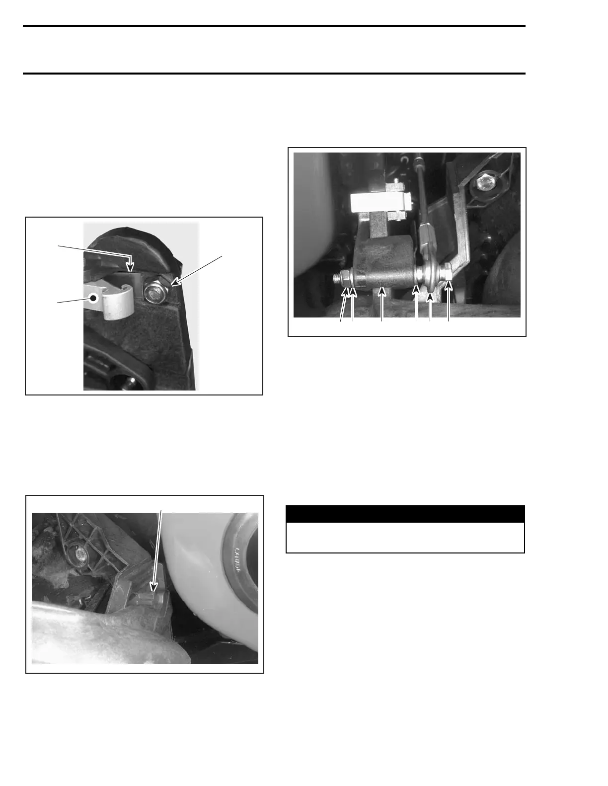
Reverse Cable
Install reverse cable to cable lever as per following
illustration.
1. Bolt
2. Ball joint
3. Cable lever
4. Flat washer
5. Lock nut
CAUTION: Ensure cable ball joint is parallel to
cable lever (90° ± 5°) to minimize tension on ca-
ble. Adjust as required.
ADJUSTMENT
Put shift lever in forward position.
Pull shift lever approximately 50 mm (2 in) and
push it back slowly in forward position.
The pawl lock no. 7 must be engaged in the an-
chor no. 22.
WARNING
When adjusting reverse cable, make sure le-
ver is well engaged into the spring slot.
F07J08A
453421
 Loading...


