Section 05 ENGINE (4-TEC)
Subsection 02 (LEAK TEST)
05-02-2 SMR2003-014_05_02A.FM
PROCEDURE
The following procedure has to be performed for
each cylinder separately, because of the 120° off-
set between the TDCs.
Rotate crankshaft counterclockwise using drive
shaft adaptor (P/N 529 035 892) until the cylinder
no. 3 is at top dead center (TDC) compression
stroke.
NOTE: Cylinder numbers are molded on valve cover.
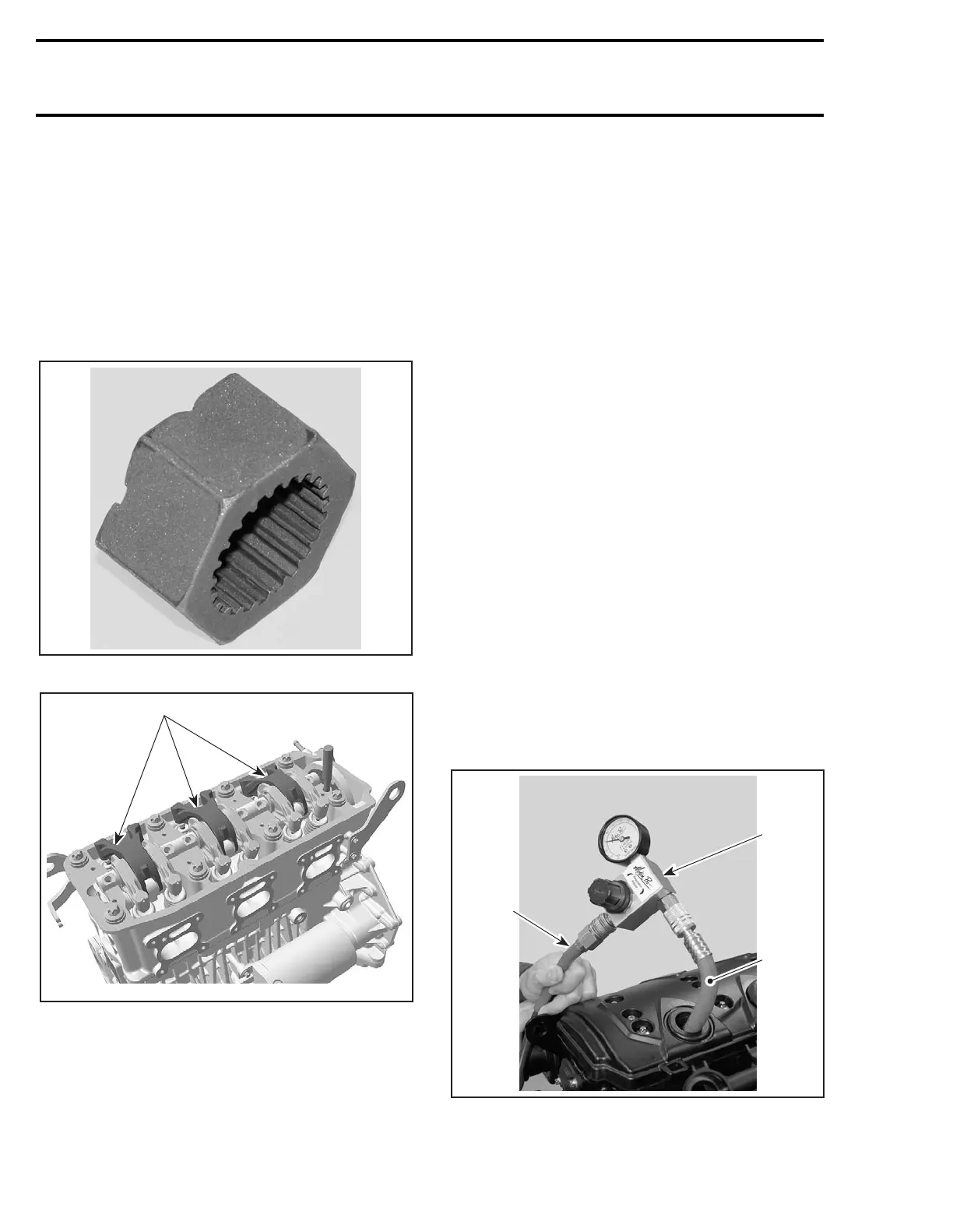
DRIVE SHAFT ADAPTOR (P/N 529 035 892)
1. Intake rocker arms
As the engine is turned over, observe the move-
ment of intake rocker arm of the cylinder no. 3.
After it completes the cycle and the intake valve
closes, observe the piston. When it reaches its up-
permost position that is TDC compression stroke.
Then perform the leak test on cylinder no. 3 as men-
tioned below.
To perform the leak test on cylinder no.1, rotate the
crankshaft counterclockwise to 240° so that the
cylinder no.1 is at TDC compression stroke. Fol-
low the instructions mentioned below to check
the leakage.
Rotate crankshaft counterclockwise to 240° so
that the cylinder no. 2 is at top dead center (TDC)
compression stroke. Follow the below given pro-
cedure to check the leakage.
The following procedure should be done for each
cylinder separately after positioning them at TDC
compression stroke, as per the procedure given
above.
Hold the crankshaft in this position by using drive
shaft adaptor (P/N 529 035 892).
Install gauge adapter into previously cleaned spark
plug hole.
Connect to adequate air supply.
NOTE: Each tester will have specific instruction
on the gauge operation and required pressure.
Set needle of measuring gauge to zero.
Supply combustion chamber with air.
1. Measuring gauge
2. Adequate adapter for spark plug hole
3. Air supply
1
R1503motr157A
2
3
 Loading...


