Section 07 ENGINE MANAGEMENT (DI)
Subsection 03 (COMPONENT INSPECTION AND ADJUSTMENT)
07-03-4 SMR2003_024 _07_03A.FM
QUICK FUEL PRESSURE TEST
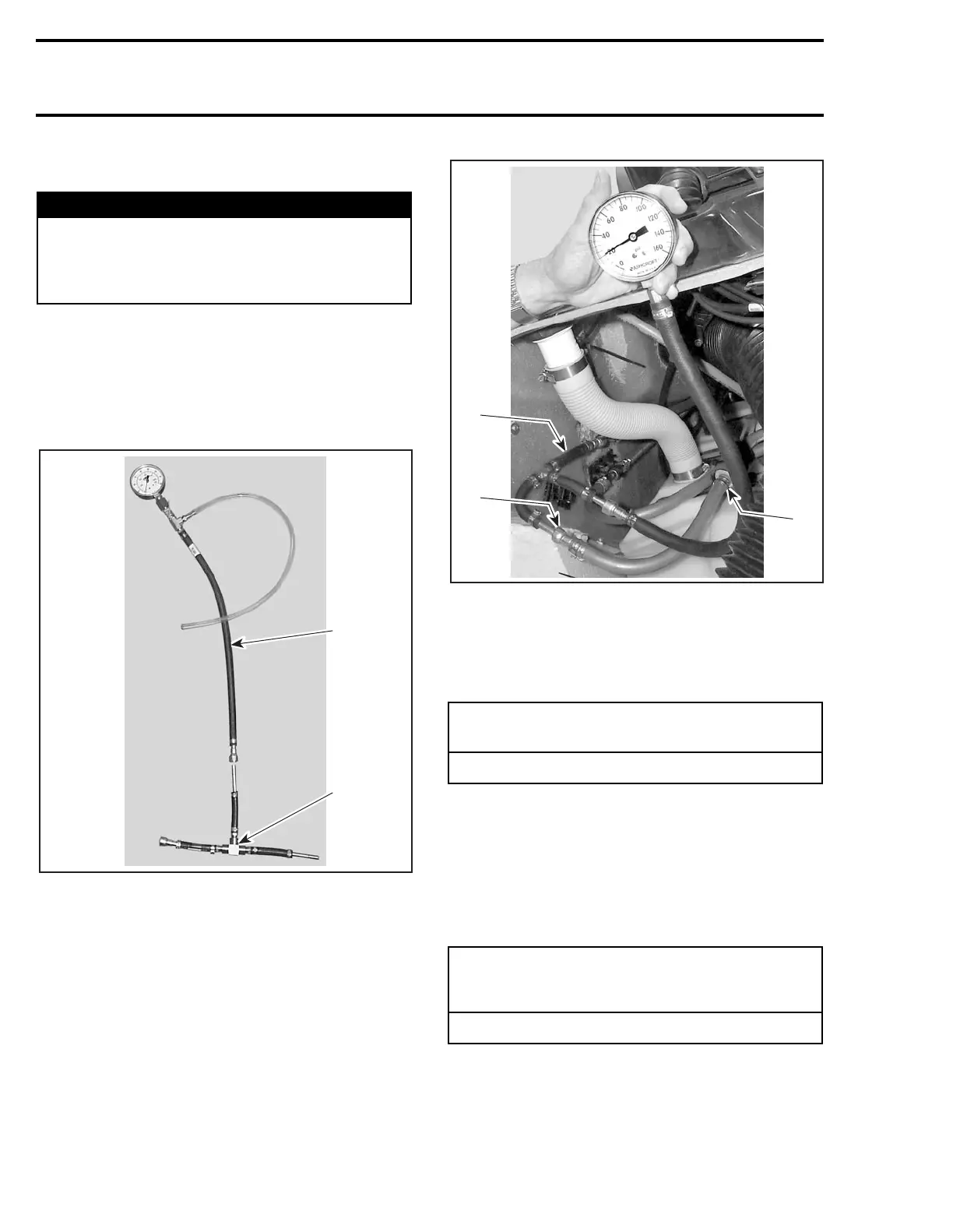
Disconnect outlet hose (the one with the fuel fil-
ter) from fuel pump using tool (P/N 529 035 714).
Connect adapter to pressure gauge as shown.
NOTE: On XP DI models, remove seat and rub-
ber plug underneath to gain access to fuel pump
and hoses.
1. Pressure gauge (P/N 529 035 709)
2. T-adapter (P/N 529 035 710)
Install pressure gauge between disconnected hose
(inline installation).
TYPICAL
1. Fuel filter
2. Fuel line going to air/fuel rail
3. Pressure gauge between disconnected hose (inline installation)
Install safety lanyard and observe fuel pressure.
Do not crank engine.
If pressure is within limits, air/fuel rail is working
adequately. Proceed with the fuel pressure test
below.
If pressure is out of limits, refer to FUEL DELIV-
ERY below and proceed with the tests described
there.
Crank or start engine and observe fuel pressure.
If pressure is within limits, fuel and air systems are
working adequately. No subsequent tests are nec-
essary for the air/fuel system.
Remove pressure gauge and reinstall fuel hose. At
installation apply engine oil on O-ring.
If pressure is out of limits, proceed with all the tests.
WARNING
Read PRESSURE TEST under AIR/FUEL RAIL
further in this section for precautions and
setup to take care of, before performing this
test. The procedure here is a quick summary.
FUEL REGULATOR PRESSURE
(when installing safety lanyard)
185 ± 14 kPa (27 ± 2 PSI)
FUEL PRESSURE
(when cranking engine
or when engine is running)
738 ± 14 kPa (107 ± 2 PSI)
2
3
1
F12R09A
 Loading...


