Section 08 ENGINE MANAGEMENT (4-TEC)
Subsection 03 (COMPONENT INSPECTION AND ADJUSTMENT)
08-03-26 SMR2003_027 _08_03A.FM
KNOCK SENSOR (KS)
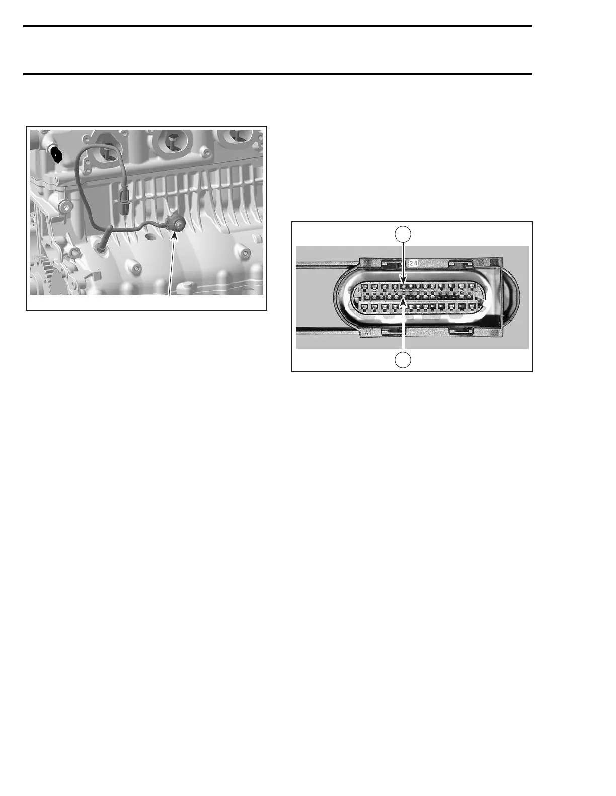
1. Knock sensor (KS)
Dynamic Test
Using the vehicle communication kit (VCK) with
the B.U.D.S. software, monitor the knock sensor
using the Faults section.
Start the engine and bring engine RPM above
5000 RPM. If no fault code occurs, the knock sen-
sor is good.
Otherwise, do the following.
Ensure sensor and cylinder head contact surfaces
are clean and mounting bolt and washer are correct
and properly torqued down.
NOTE: It is necessary to remove intake manifold
to inspect contact surfaces. Refer to INTAKE SYS-
TEM section.
Check the knock sensor resistance.
Disconnect the connector from knock sensor har-
ness.
Static Resistance Test
Using a multimeter, check the resistance between
both terminals on the knock sensor harness side.
The resistance should be approximately
5 MΩ.
If resistance is not good, replace knock sensor.
If resistance is good, reconnect the knock sensor
connector and disconnect the EMS ECU connec-
tor A from the EMS ECU.
Using a multimeter, recheck resistance value be-
tween terminals 9 and 23.
If wiring harness is good, try a new EMS ECU. Re-
fer to EMS ECU REPLACEMENT procedures else-
where in this section.
Otherwise, repair the connector or replace the wir-
ing harness between EMS ECU connector and
knock sensor.
Replacement
Remove the intake manifold. Refer to INTAKE
MANIFOLD REPLACEMENT in INTAKE section.
Unscrew and remove knock sensor.
Clean contact surface, apply Loctite 243 in thread-
ed hole then install the new knock sensor.
Torque screw to 24 N•m (18 lbf•ft).
CAUTION: Improper torque might prevent sen-
sor to work properly and lead engine to severe
damage of internal components.
Replug connector.
R1503motr188A
9
23
 Loading...


