Section 08 ENGINE MANAGEMENT (4-TEC)
Subsection 03 (COMPONENT INSPECTION AND ADJUSTMENT)
SMR2003_027 _08_03A.FM 08-03-17
Connect the CPS, KS, OPS, and the MAPS to the
wiring harness.
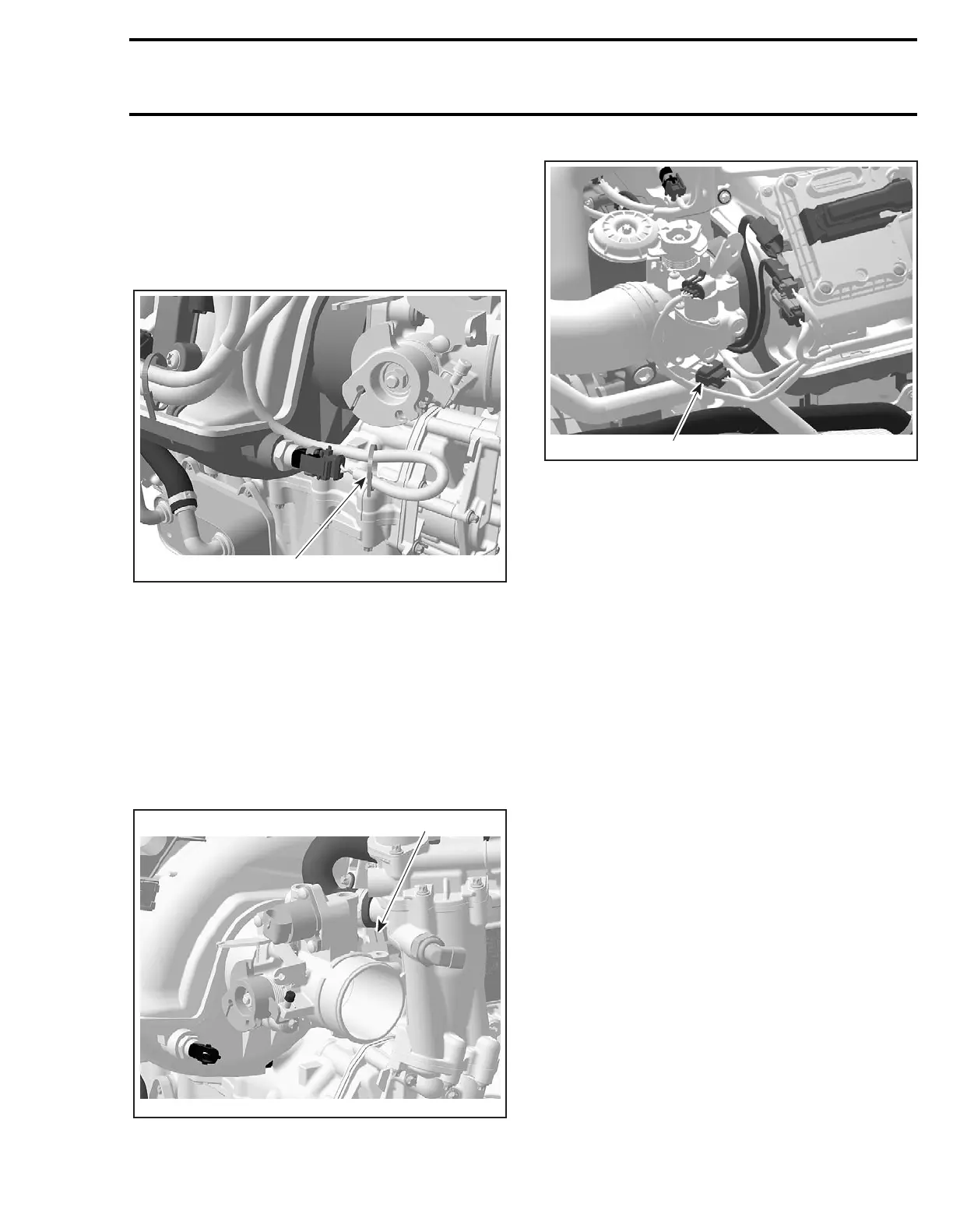
Also connect now the MATS, TPS, OSPS, idle by-
pass and TOPS valve to the wiring harness.
Fix the wiring for the MATS with a locking tie to
support the cables.
1. Locking tie
Install all remaining parts, which has been removed.
THROTTLE POSITION SENSOR
(TPS)
General
The throttle position sensor (TPS) is a potentiom-
eter that sends a signal to the EMS ECU which is
proportional to the throttle shaft angle.
4-TEC ENGINES
1. Throttle position sensor (TPS)
4-TEC SUPERCHARGED ENGINES
1. Throttle position sensor (TPS)
IMPORTANT: Prior to testing the TPS, ensure that
mechanical components/adjustments are adequate
according to THROTTLE BODY in AIR INDUCTION
SYSTEM above.
The EMS may generate several fault codes pertain-
ing to the TPS. Refer to SYSTEM FAULT CODES in
DIAGNOSTIC PROCEDURES section for more in-
formation.
Wear Test
While engine is not running, activate throttle and
pay attention for smooth operation without physi-
cal stops of the cable.
Using the vehicle communication kit (VCK) with
the B.U.D.S. software, use the Throttle Opening
display under Monitoring.
Slowly and regularly depress the throttle. Observe
the needle movement. It must change gradually
and regularly as you move the throttle. If the nee-
dle “sticks”, bounces, suddenly drops or if any dis-
crepancy between the throttle movement and the
needle movement is noticed, it indicates a worn
TPS that needs to be replaced.
1
R1503motr204A
1
R1503motr165A
1
R1503motr271A
 Loading...


