Section 05 ENGINE (4-TEC)
Subsection 08 (CYLINDER HEAD AND VALVES)
SMR2003-020_05_08A.FM 05-08-11
Installation
For installation, reverse the removal procedure.
Pay attention to the following details.
Grease the camshaft bearing journals well by us-
ing the grease Klueber Isoflex (P/N 293 550 021)
or a similar product.
Install camshaft then place the camshaft lock no. 20
in the slot.
1. Camshaft lock position
For other parts, refer to proper installation proce-
dure.
VALVE SPRING
Removal
Remove:
– rocker arms
– cylinder head.
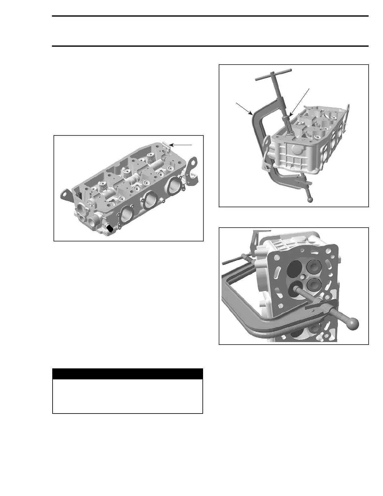
Compress valve springs no. 22 and no. 23. Use
valve spring compressor clamp (P/N 529 035 724)
and valve spring compressor cup (P/N 529 035
725).
1. Valve spring compressor clamp
2. Valve spring compressor cup
LOCATE VALVE SPRING COMPRESSOR CLAMP IN CENTER OF
THE VALVE
Remove valve cotters no. 24.
WARNING
Always wear safety glasses when disassem-
bling valve springs. Be careful when unlock-
ing valves. Components could fly away be-
cause of the strong spring preload.
1
R1503motr101B
2
1
R1503motr103A
R1503motr104A
 Loading...


