Section 05 ENGINE (4-TEC)
Subsection 07 (LUBRICATION SYSTEM)
05-07-16 SMR2003-019_05_07A.FM
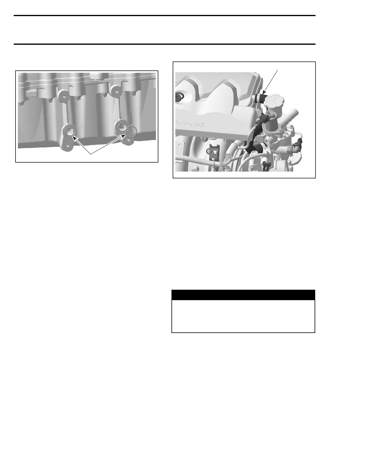
– O-rings no. 38.
1. O-rings
Inspection
If O-rings are brittle, cracked or hard, replace them.
Clean both contact surfaces of oil cooler.
Check and clean the oil inlet and outlet area for dirt
and other contaminations.
Installation
For installation, reverse the removal procedure.
Pay attention to the following details.
Apply grease on O-rings.
Torque oil pump cover screws to 10 N•m (88 lbf•in).
Apply Loctite 243 (blue) on threads.
OIL SEPARATOR
Pressure Test
Refer to ENGINE MANAGEMENT section.
Removal
– Remove TOPS ventilation hose no. 7.
TYPICAL
1. TOPS ventilation hose
– Disconnect wiring harness from TOPS valve
no. 8 and OSPS no. 9.
– Detach air silencer from throttle body.
– Disconnect battery cables and vent tube then
remove battery. Refer to BATTERY in CHARG-
ING SYSTEM section for proper procedures.
– Remove retaining screws no. 42.
– Place rags under cover to prevent spillage. If
spillage occurs, clean immediately with the pul-
ley flange cleaner (P/N 413 711 809) to prevent
stains.
– Remove suction pump cover with oil separator
ass’y.
– Remove TOPS valve no. 8 from oil separator
ass’y. Refer to TOPS VALVE in ENGINE MAN-
AGEMENT section.
– Completely disassemble oil separator ass’y.
WARNING
Wear safety glasses and work in a well venti-
lated area when working with strong chemical
products. Also wear suitable non-absorbent
gloves to protect your hands.
1
R1503motr133A
 Loading...


