Section 09 COOLING SYSTEM
Subsection 02 (CIRCUIT, COMPONENTS AND CARE)
SMR2003-029_09_02A.FM 09-02-25
Inspection
Check if gasket no. 7 is brittle, hard or damaged
and replace as necessary.
1. Weep hole pump housing gasket
Check if thermostat is in good condition. Refer to
THERMOSTAT elsewhere in this section.
Installation
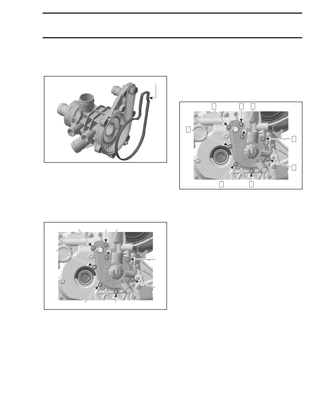
The installation is the opposite of the removal pro-
cedure. Install screws as per the following illustra-
tion.
1. Screws M6 x 25
2. Screws M6 x 105
CAUTION: To prevent leaking, take care that
the gaskets are exactly in groove when you re-
install the coolant pump housing.
Apply Loctite 243 on screw threads and torque to
10 N•m (88 lbf•in).
Tightening sequence for screws on coolant pump
housing is as per following illustration.
THERMOSTAT
The thermostat is a single action type.
Removal
Remove the coolant pump housing from the PTO
cover. Refer to COOLANT PUMP HOUSING RE-
MOVAL elsewhere in this section.
NOTE: The thermostat is located inside the cool-
ant pump housing.
1
F18E11A
1
2
F18E10A
1
1
1
1
2
1
F18E10B
32
4
5
1887
6
 Loading...


