Section 12 ELECTRICAL SYSTEM
Subsection 04 (STARTING SYSTEM)
SMR2003-037_12_04A.FM 12-04-7
STARTER DISASSEMBLY
717 and 787 RFI Engines
Before disassembling, trace index marks on yoke
no. 1 and clutch housing no. 10 to ease further
assembly.
TYPICAL
1. Trace indexing marks
Remove starter support nuts no. 12 then through
bolts no. 5. Separate end frame no. 3 from yoke
assembly no. 1. Withdraw yoke assembly from ar-
mature no. 11.
Brush holder no. 2 can be removed from end frame
no. 3 by unscrewing nut retaining terminal.
Check that the radial play between the armature
shaft and end frame is not greater than 0.20 mm
(.008 in). Replace end frame if so.
Tap the pinion stop collar no. 7 using a screwdriv-
er. Remove circlip no. 6. Disassemble pinion stop
collar no. 7 and spring no. 8.
1. Pinion stop collar
Turn clutch assembly no. 9 clockwise to remove
it from armature assembly no. 11.
Pull housing from armature.
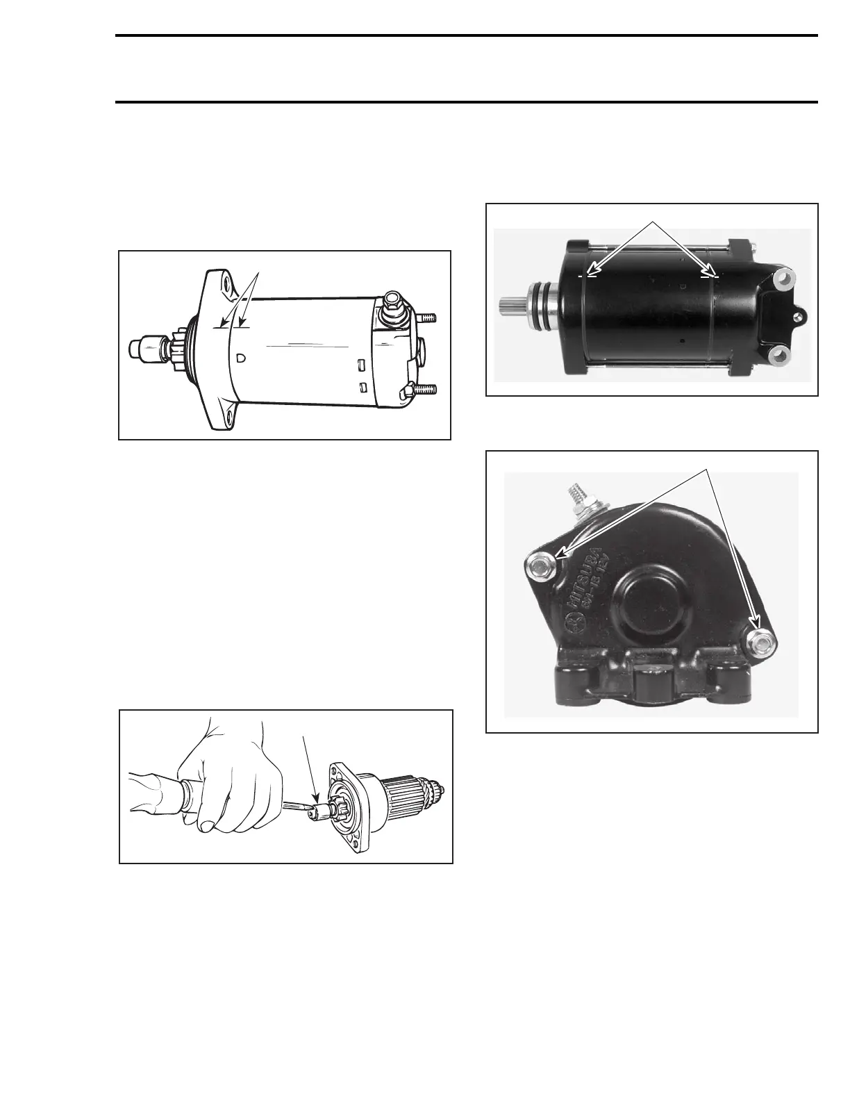
947 DI Engines
Locate index marks on yoke no. 1 and end covers
no. 3 and no. 10.
1. Index marks
Loosen through bolts no. 5.
1. Through bolts
Remove end cover no. 3 and gasket on armature
shaft side.
F01H0PA
1
A03E04A
1
F06H1FA
1
F06H1GA
1
 Loading...


