Section 08 ENGINE MANAGEMENT (4-TEC)
Subsection 03 (COMPONENT INSPECTION AND ADJUSTMENT)
SMR2003_027 _08_03A.FM 08-03-15
ENGINE WIRING HARNESS
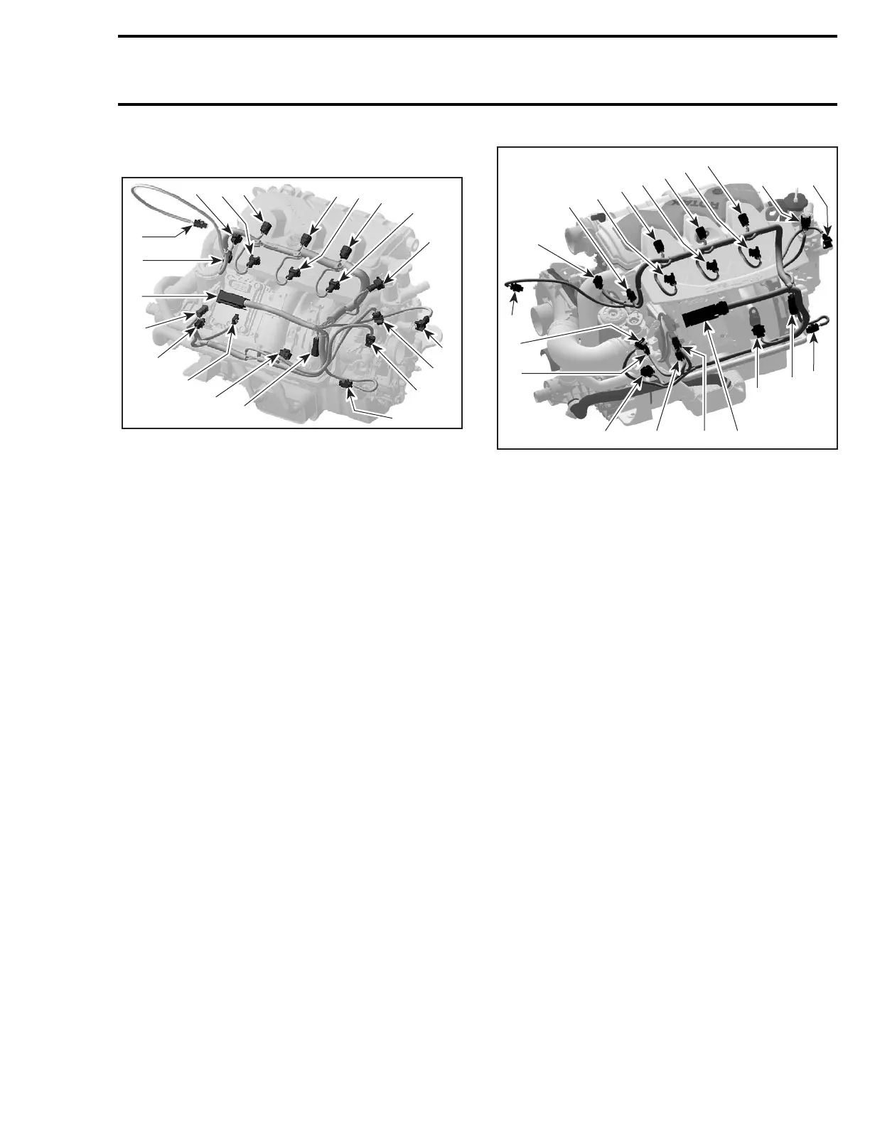
4-TEC ENGINES
1.EMS ECU connector
2.CTS connector
3.EGT connector
4.CAPS connector
5.Fuel injector connector (cylinder 1)
6.Ignition coil connector (cylinder 1)
7.Fuel injector connector (cylinder 2)
8.Ignition coil connector (cylinder 2)
9.Fuel injector connector (cylinder 3)
10.Ignition coil connector (cylinder 3)
11.TOPS valve connector
12.OSPS connector
13.TPS connector
14.Idle bypass valve connector
15.MATS connector
16.Engine connector
17.MAPS connector
18.OPS connector
19.KS connector
20.CPS connector
4-TEC SUPERCHARGED ENGINES
1.EMS ECU connector
2.CTS connector
3.EGT connector
4.CAPS connector
5.Fuel injector connector (cylinder 1)
6.Ignition coil connector (cylinder 1)
7.Fuel injector connector (cylinder 2)
8.Ignition coil connector (cylinder 2)
9.Fuel injector connector (cylinder 3)
10.Ignition coil connector (cylinder 3)
11.TOPS valve connector
12.OSPS connector
13.TPS connector
14.Idle bypass valve connector
15.MATS connector
16.Engine connector
17.MAPS connector
18.OPS connector
19.KS connector
20.CPS connector
Resistance Test
Check continuity of the circuits according to the
wiring diagram in the WIRING DIAGRAMS section
of this manual.
If wiring harness is good, check the respective
sensor/actuator as described in this section.
Otherwise, repair the connectors, replace the wir-
ing harness or the EMS ECU/MPEM as diagnosed.
4
R1503motr199A
5
6
78
10
9
11
12
3
2
1
19
20
18
17
14
13
15
16
13
4
R1503motr270A
3
2
5
6
7
8
9
10
11
12
14
18
19 20 1
16
15
17
 Loading...


