Section 13 PROPULSION SYSTEM
Subsection 05 (VARIABLE TRIM SYSTEM)
SMR2003-043_13_05A.FM 13-05-3
GENERAL
To test VTS control module, motor or switch, refer
to INSTRUMENTS AND ACCESSORIES.
To have access to VTS module, remove seat on
RX DI models and remove rear access cover on
XP DI).
REMOVAL
All Models
Remove nut no. 14 and bolt no. 13 retaining VTS
rod no. 1 to sliding shaft no. 10.
Remove clamps no. 2.
Remove boot no. 3.
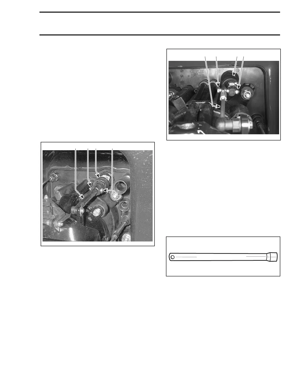
RX DI MODELS
1. VTS rod
2. Bolt
3. Lock nut
4. Rubber boot
XP DI MODELS
1. VTS rod
2. Bolt
3. Lock nut
4. Rubber boot
RX DI Models
Disconnect:
– steering cable
– reverse cable.
Unscrew the pivot arm bolts (one on each side).
Move the pivot arm backwards.
All Models
To loosen nut no. 4, use VTS socket tool (P/N 295
000 133).
Remove sealing washer no. 5.
All Models
Disconnect wiring harnesses.
Pull out VTS assembly no. 6 from bilge.
1
F16J0AA
3
4
2
F06J01E
1
2
3
4
F01B2PA
 Loading...


