Section 05 ENGINE (4-TEC)
Subsection 05 (REMOVAL AND INSTALLATION)
SMR2003-017_05_05A.FM 05-05-1
REMOVAL AND INSTALLATION 0
GENERAL
Engine removal is necessary to repair BOTTOM
END.
ENGINE REMOVAL
Use the VCK (Vehicle Communication Kit) (P/N 529
035 844) and release the fuel pressure in the fuel sys-
tem. Refer to ENGINE MANAGEMENT section.
In order to remove engine from watercraft proceed
as follows.
First, disconnect battery cables from battery.
Electrical Connections
It is recommended to disconnect electrical con-
nections prior to disconnecting fuel lines.
Disconnect magneto wiring harness.
Disconnect the throttle position sensor (TPS),
manifold air pressure sensor (MAPS) and manifold
air temperature sensor (MATS) (refer to INTAKE
section).
Refer to ENGINE MANAGEMENT for location of sen-
sors and connectors.
O.P.A.S.
To disconnect O.P.A.S., refer to STEERING section.
Jet Pump Removal
To withdraw jet pump, refer to PROPULSION
section.
CAUTION: Whenever removing engine from
watercraft, engine/jet pump alignment must be
performed at reinstallation.
Drive System
To withdraw drive shaft, refer to PROPULSION
section.
Cooling System
To remove cooling system hoses, refer to COOL-
ING SYSTEM section
Exhaust Pipe
To remove exhaust pipe, refer to EXHAUST SYS-
TEM in ENGINE section.
Intake Manifold
To remove intake manifold, refer to INTAKE sec-
tion.
On Supercharged models, remove inlet tube
from supercharger and air duct.
Engine Support
NOTE: Be careful when removing engine sup-
port(s) or rubber mount adapters, shims could
have been installed underneath. Shims control
engine/jet pump alignment. Always note position
of shims for reinstallation, to avoid altering engine
alignment.
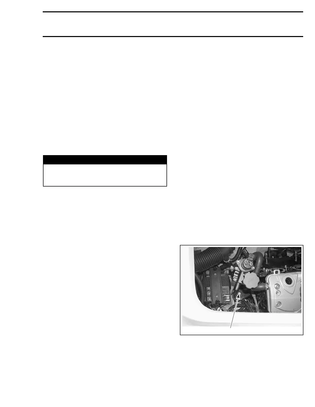
Remove engine support mount screws.
FRONT SUPPORT
1. Remove screw
WARNING
Always disconnect battery cables exactly in
the specified order, BLACK negative cable
first then the RED positive battery cable last.
1
F18D13A
 Loading...


