Section 09 COOLING SYSTEM
Subsection 02 (CIRCUIT, COMPONENTS AND CARE)
09-02-20 SMR2003-029_09_02A.FM
947 DI ENGINES — XP DI MODELS
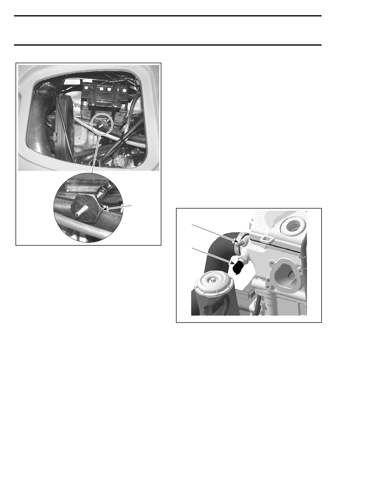
1. Hose pincher on water supply hose
CAUTION: When finished towing the watercraft,
the hose pincher must be removed before oper-
ating it.
1503 Engines
CIRCUIT
Closed Loop System
A closed loop cooling system is utilized on the
1503 4-TEC engines, which offers an efficient en-
gine cooling while keeping dirt and salt water out
of the cooling system. This system keeps the tem-
perature constant and prevents internal engine
corrosion.
A separate coolant expansion tank ensures that
enough engine coolant is in the circuit during any
operating condition.
The coolant flow comes from the coolant pump
impeller into the engine block. It goes around the
cylinders and straight up to the cylinder head. A
smaller quantity of engine coolant enters the en-
gine block on the exhaust side for a better cooling.
In the cylinder head the water channels flow
around the exhaust and then the intake valves and
leave the engine through a large hose. From there
the coolant goes back to the water pump housing
and depending on the engine temperature, it
flows through the thermostat directly back to the
water pump impeller, or it takes its way through
the ride plate which operates as a heat exchanger.
A smaller quantity of engine coolant is also direct-
ed towards the oil cooler, which is located under
the air intake manifold, to increase cooling effi-
ciency.
Coolant temperature sensor and bleed nipple are
located on the cylinder head.
1. Bleed nipple
2. Coolant temperature sensor (CTS)
CAUTION: Never modify cooling system ar-
rangement, otherwise serious engine damage
could occur.
Pressure Cap
Check if cap pressurize the system. if not, install
a new 90 kPa (13 PSI) cap (do not exceed this pres-
sure).
1
F18E0XA
2
 Loading...


