Section 07 ENGINE MANAGEMENT (DI)
Subsection 03 (COMPONENT INSPECTION AND ADJUSTMENT)
SMR2003_024 _07_03A.FM 07-03-23
ELECTRONIC MANAGEMENT
MPEM REPLACEMENT
General
Prior to replacing a suspected MPEM, ensure that
all the recommendations in the general introduc-
tion of this section have been followed.
IMPORTANT: When MPEM is replaced, the TPS
closed position and the TDC setting must be re-
programmed/reset. Refer to their specific section
for adjustment.
To allow transferring the previous recorded infor-
mation from the old MPEM to the new one, use the
vehicle communication kit (VCK) with the B.U.D.S.
software. Use MPEM Replace in the Module
menu. Follows instructions in its help system.
NOTE: If the old MPEM is working, it must be read
inside B.U.D.S. prior to removing it from the vehicle
to carry vehicle information and history to the new
MPEM. Besides, select the Setting tab and note
the Current Angle in the ignition offset area. When
installing the new MPEM, re-use this setting as a
preliminary setting. Then, proceed with the regular
procedure for the TDC setting.
If the old MPEM is not working, try to find a previous
saved file from B.U.D.S. Otherwise, perform the op-
erations described in IF THE PREVIOUS MPEM
WAS NOT READ WITH B.U.D.S. below.
Replacement
Disconnect battery cables.
Disconnect AMP connectors from MPEM.
Remove MPEM.
Install the new MPEM on the vehicle.
Reconnect AMP connectors to MPEM then bat-
tery cables.
If the previous MPEM was read with B.U.D.S.
Transfer the data from the previous MPEM to the
new one using B.U.D.S. then proceed with the re-
quired resets after following the procedure in VAL-
IDATING TPS SYNCHRONIZATION below.
If the previous MPEM was NOT read with
B.U.D.S.
– Enter the vehicle and engine serial numbers in
the Vehicle tab.
– Enter the old MPEM serial number in the Part
Replacement under History tab. Click on Add
part in History.
– Reprogram safety lanyard(s).
NOTE: The MPEM serial number can be found on
the MPEM sticker that also shows the P/N.
Continue procedure as per VALIDATING TPS SYN-
CHRONIZATION below.
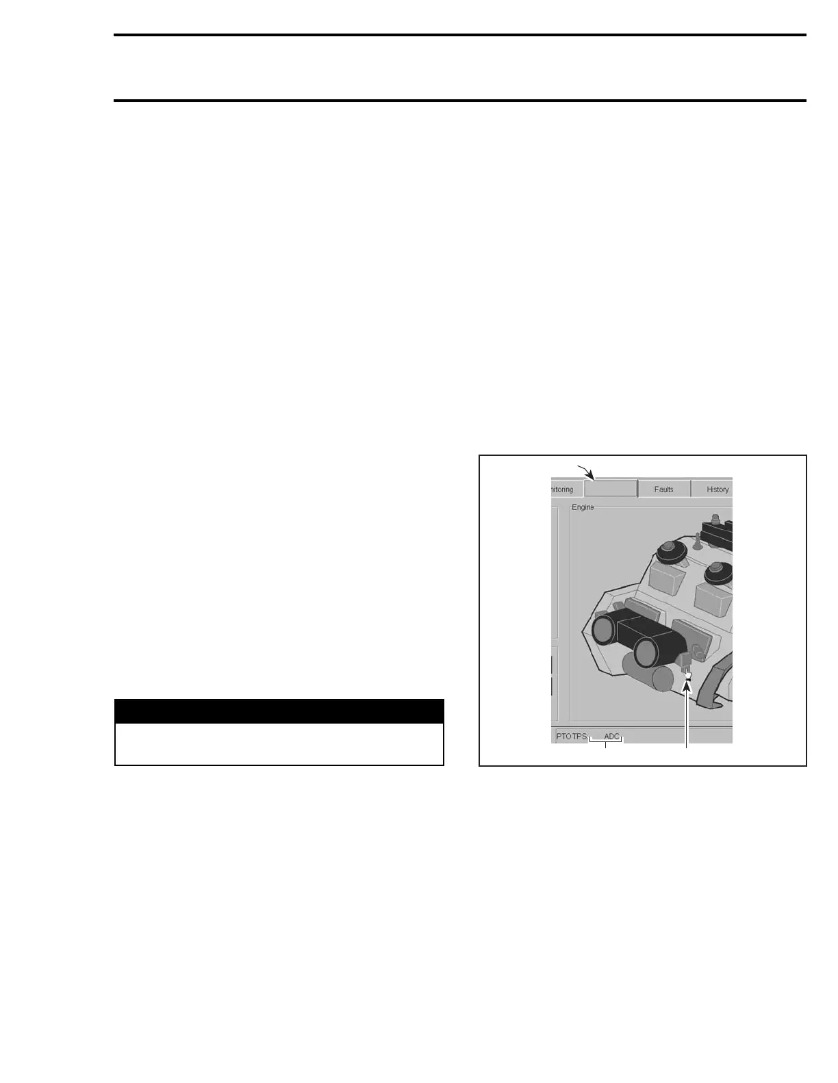
Validating TPS Synchronization
Select the Activation tab.
Point the mouse cursor over the PTO TPS. Check
the ADC reading. It must be between 23 and 45.
1. “Activation” tab
2. Point on PTO TPS
3. ADC reading
Point the mouse cursor over the MAG TPS. Check
the ADC reading. It must be between 37 and 59.
If either readings are not within those parameters,
they are out of range and the MPEM will be unable
to initialize. Proceed with THROTTLE BODY SYN-
CHRONIZATION as detailed in THROTTLE BODY.
If the ADC’s are within range, proceed with the
required resets.
After performing the required resets, ensure to
clear all faults from the newly replaced MPEM.
Now, all faults must be inactive (except the Diag-
nostic Cap Missing fault).
WARNING
Battery BLACK negative cable must always
be disconnected first and connected last.
Activation
30
1
3
F12R1JA
2
 Loading...


