Section 05 ENGINE (4-TEC)
Subsection 06 (PTO HOUSING/MAGNETO)
05-06-6 SMR2003-018_05-06A.FM
Installation
For installation, reverse the removal procedure.
However, pay attention to the following.
Torque PTO coupling to 250 N•m (184 lbf•ft). Ap-
ply Loctite anti-seize on threads.
STATOR
Removal
Remove:
– PTO housing (refer to PTO HOUSING REMOVAL
elsewhere in this section)
– holding plate no. 14 with CPS no. 15
TYPICAL
1. CPS screws
2. Holding plate
3. CPS
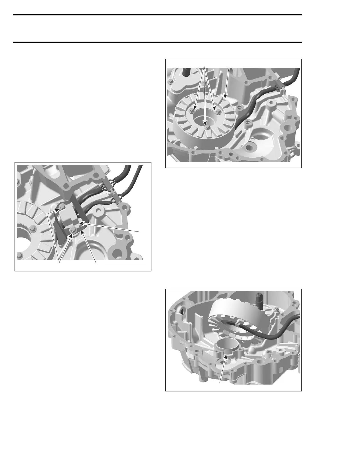
– screws no. 16
– stator no. 17.
TYPICAL
1. Stator screws
2. Stator
Inspection
Check stator and CPS condition. If damaged re-
place the faulty part.
For electrical inspection, refer to CHARGING SYS-
TEM for the stator and to ENGINE MANAGEMENT
for the CPS.
Installation
For installation, reverse the removal procedure.
However, pay attention to the following.
NOTE: There is only one position for the stator
(notch in the magneto housing cover).
TYPICAL
1. Notch for stator
1
R1503motr26A
2
1
R1503motr51A
 Loading...


