Section 14 WIRING DIAGRAMS
Subsection 01 (WIRING DIAGRAMS)
SMR2000-073_14_01A.FM 14-01-3
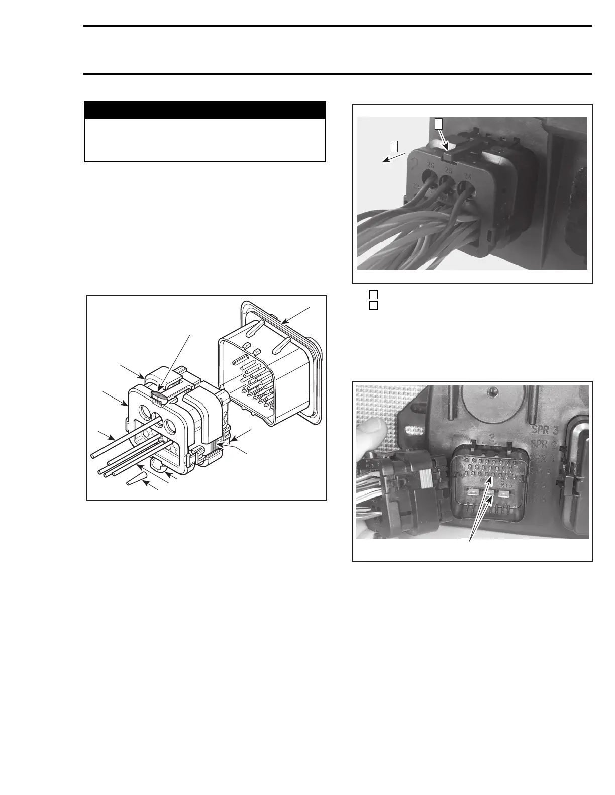
AMP PLUG CONNECTOR
These connectors are found on the MPEM.
When servicing electrical system, special care
must be taken when working with AMP Plug Con-
nectors in order to prevent any malfunction of the
system.
Description
AMP PLUG CONNECTOR
1. Plug assembly
2. Cover assembly
3. Mating seal
4. Wedge lock
5. Header assembly
6. Seal plug
7. Power wire
8. Signal wire
9. Locking tab
Removal
To remove the plug connector from the header as-
sembly, press both tabs and pull plug.
Step : Press tabs (both sides)
Step : Pull plug
Installation
Apply a thin coat of DEOXIT contact lubricant (P/N
293 550 015) to the pins of the header on the
MPEM only.
1. Apply a thin coat of DEOXIT contact lubricant
CAUTION: Do not apply lubricant excessively.
Care must be taken so that the lubricant will not
come in contact with the mating seal; the seal
may loose its sealing capacities. Do not apply
lubricant on contacts inside plug connector.
WARNING
Ensure all terminals are properly crimped on
wires and connector housings are properly fas-
tened.
F00H0WB
2
3
4
5
6
7
8
9
9
1
F00H0NA
1
2
1
2
F00H11A
1







 To Next Page