15
Compressor and Compressor Enclosure
The Eclipse compressor is a two-cylinder, variable speed wobble piston compressor, driven by a highly
efficient Brushless DC (BLDC) motor. When air flows into the compressor enclosure, it passes through
an air intake filter/muffler that muffles sound and filters out impurities. Using one cylinder, the
compressor takes in filtered air and delivers it to the ATF Module under pressure. The second cylinder
draws a vacuum on the ATF module and exhausts nitrogen rich gas to the exhaust vent.
Using a multifaceted approach, sound, heat, and vibration generated by the compressor are mitigated by
the compressor enclosure. Vibration and structure-borne noise are addressed by the dual axis gimbal
that supports the compressor and the tubing that connects the compressor to the ATF module. The rigid
walls of the compressor enclosure and the sound adsorbing foam that lines it diminish the radiated noise.
The centrifugal blower mounted within the compressor enclosure serves to efficiently draw cooling air in
over the compressor cylinders while simultaneously pushing exhaust gas out of the concentrator.
Power Distribution
The Power Manager takes external power that comes into the Eclipse from the power supplies or Power
Cartridge and monitors and controls power distribution to the rest of the Eclipse system. The Power
Manager drives the compressor, ATF module motor, blower, and provides power to the control module.
In addition, when the unit is connected to an external power source, the power manager monitors and
controls the recharging of the Power Cartridge.
Control Module
The control module is at the center of nearly all Eclipse functions. The module constantly monitors
dynamics such as temperatures, pressures, product flow and concentration, and user input. It
determines proper compressor and ATF motor speeds needed in order to provide optimum system
performance. In addition, this system supports the operation of the Control Panel and its indicators.
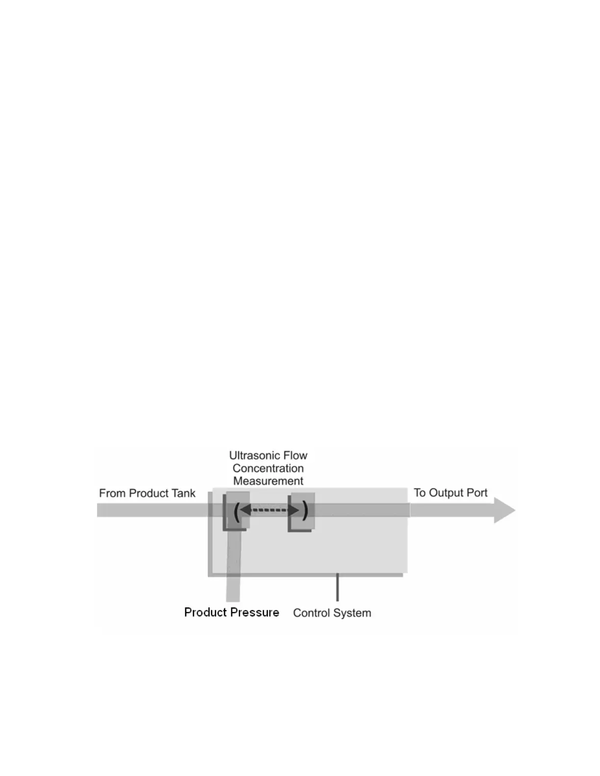
The Control Module utilizes a proprietary ultrasonic flow and concentration sensor and a flow control
valve to accurately control the flow of oxygen in Continuous and Pulse Flow Modes.
Figure 2: Flow Sensor Diagram