81
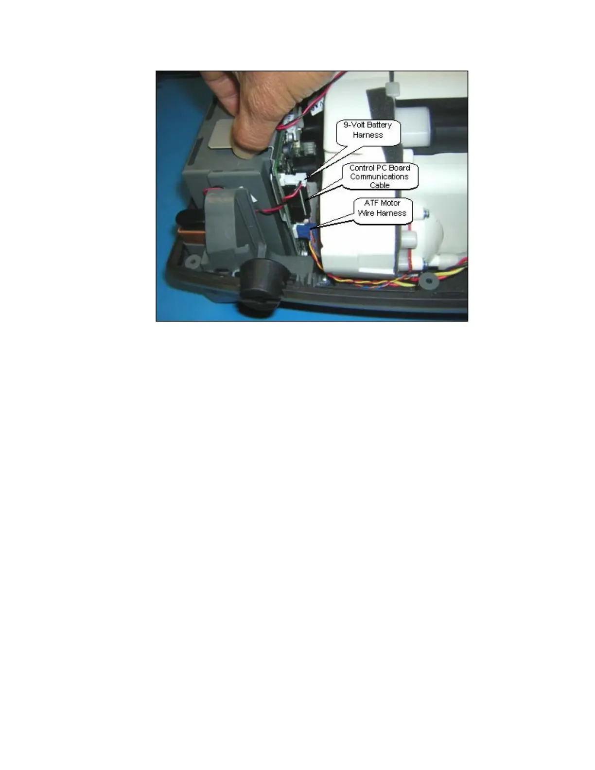
Figure 46: ATF Motor, 9-Volt Battery, and Control PC Board Communications Wire Harness Removal.
7. Position the new Power Manager PCB 1” out of the unit case as shown in Figure 47. Gently push
the Compressor Box away from the Power Manager PCB by 1/8”. Connect the 2 wire harnesses
and the ribbon cable. Position the Power Manager PCB into the slots on the Unit Case.
8. Install the fan with the 2 screws and lightly tighten as shown in Figure 44. Apply Loctite 425
Thread Locker on the tips of the screws before installing. Ensure that it is blowing down as
indicated by the arrow on the side of the Fan.
9. Install the Battery Bridge PCB and 4 wire harnesses shown in Figure 44.
10. Screw in the 4 screws shown in Figure 43.
11. Hold onto the Compressor Box and lift the Bottom Case in standing position. Insert the Exhaust
Tube into the slot of the Exhaust Duct as shown on Figure 45 above. Ensure that it is secure
without any gaps.
12. Install the Unit Cover as described in the section Remove and Replace the Unit Cover.