76
3. Lift the Control Module Assembly and disconnect the Inlet Air Temperature, Data
Communications Port, Power Manager PC Board Communications, Proportional Valve wire
harness, and Buzzer wire harnesses as shown in Figure 38.
4. Lift the control module out of the Unit. Cut the green cable tie to the silicone tube that is
connected to the sensor as shown in Figure 39. Disconnect the silicone tube that is attached to
the sensor. Cut the green cable ties to the silicone tubes that are connected to the flow tube as
shown in Figure 39. Disconnect the silicone tubes that are attached to the flow tube.
5. Pinch the silicone tube coming from the ATF product port and secure with a cable tie.
6. Remove the Control Module Assembly.
7. To install a new Control Module Assembly, cut the cable tie used to pinch the silicone tube
coming from the product tank. Attach this tube and the tubes from the Proportional Valve and
from the Product Tank to the flow tube as shown in Figure 38. Secure with a cable tie. Connect
the silicone tube to the sensor as shown in Figure 38. Secure with a cable tie. Place the 2
screws in the sheet metal bracket as shown in Figure 39. Inspect the tubing to ensure the tubing
is not kinked.
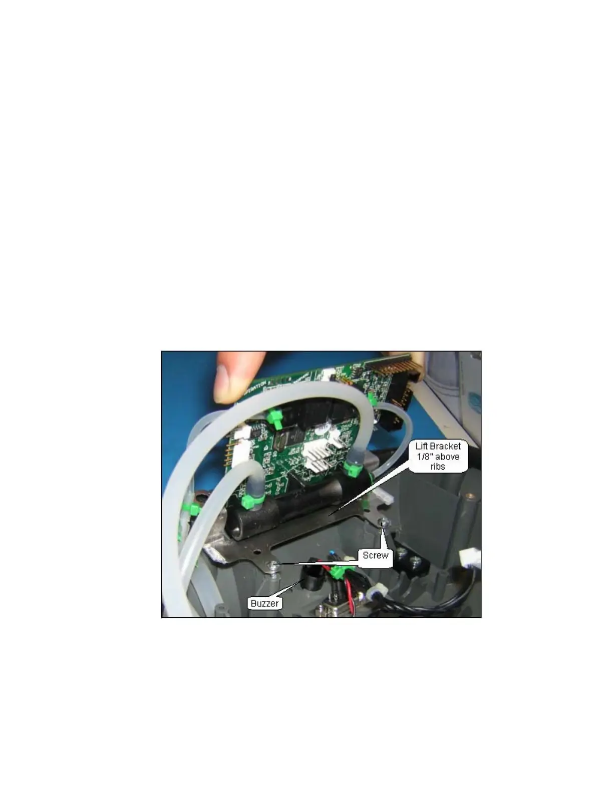
8. Lower the Control Module Assembly into the Unit Case only to where the aligning pins go through
the sheet metal bracket; make sure the sheet metal bracket is 1/8” above the supporting ribs –
this will ensure the 2 screws stay in the bracket and do not fall in the unit case as shown in Figure
39. Start the 2 screws by turning them 2 times into the unit case. After starting both screws,
lower the Control Module Assembly onto the supporting ribs; tighten the 2 screws to the unit
case.
Figure 39: Control Module Installation.
9. Connect the Inlet Air Temperature, Data Communications Port, Power Manager PC Board
Communications, Proportional Valve wire harness and Buzzer wire harnesses as shown on
Figure 38.
10. Installation of the unit cover on the unit is described in the Remove and Replace of the Unit
Cover.