86
onto a padded ESD safe surface.
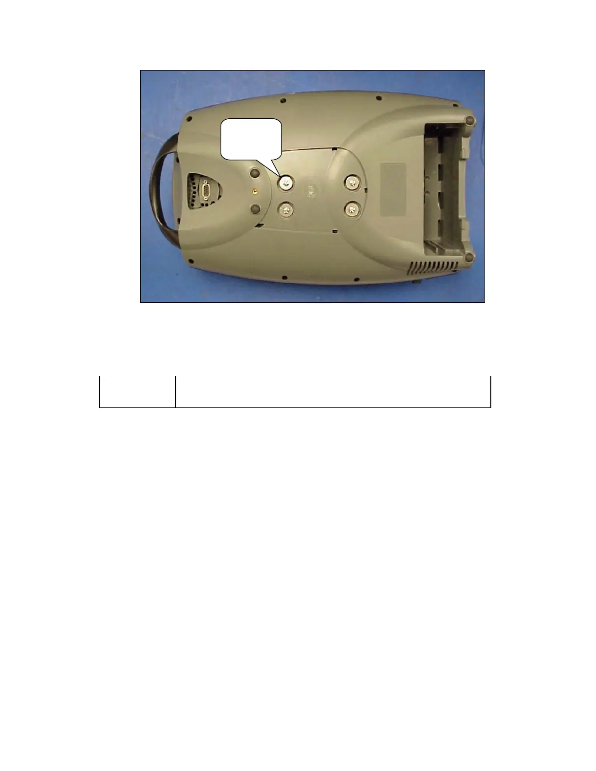
Screws
Washers
(4 places)
Figure 52: Remove Compressor Box screws.
7. Remove the Compressor Box.
NOTE:
There are no field serviceable parts inside the Compressor Box. Do
not attempt to disassemble or modify the Compressor Box in the field.
8. To install the Compressor Box, Lay the new Compressor Box in the Unit. Turn over the Unit.
9. Position the Compressor Box into the Bottom Case with the compressor box screw holes aligned
with the 4 brass eyelets. Screw in the 4 screws and 4 washers as shown in Figure 52. Apply
small amount of Loctite 425 on the threaded tips of the screw before installing.
10. Install the braided tubes into the ATF pressure and vacuum ports as shown on Figure 51 above.
Secure joints with cable ties.
11. Use a cable tie to secure the silicone tube to the braid tube to ensure that there is NO kinking on
the bend as shown on Figure 51 above. Hand tightens the cable tie. Inspect the tubing to ensure
the tubing is not kinked.
12. Hold onto the Compressor Box and lift the Bottom Case into a standing position. Insert the
Exhaust Tube into the slot of the Exhaust Duct as shown on Figure 50 above. Ensure that it is
secure without any gaps.
13. Plug the 3 harnesses into the Power Manager PCB as shown on Figure 49 above.
14. Install the Case Bottom Cover as shown in Figure 48.
15. Install the Unit Cover as described in the section Remove and Replace the Unit Cover.