2.36
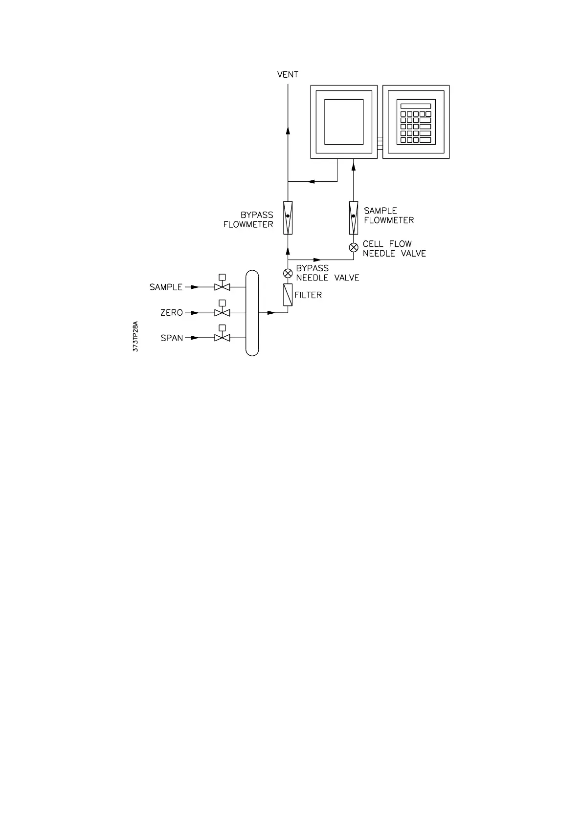
Figure 2.16 Fast-loop Manifold System
Care must be taken to ensure that the relay ratings are not exceeded otherwise the relays will
be damaged. This is especially so when inductive loads are being switched.
It will be necessary to fit spark suppressors across the coils of the solenoid valves. For ac
supplies, suitable ones are 0.047: F capacitors in series with 100 ohm resistors. They can be
obtained from Servomex under part no. 2692-0029. For dc supplies suppressing diodes are
required.
The cable must not be installed close to other equipment likely to generate severe levels of
electromagnetic interference. Where this is unavoidable, a shielded cable should be used and
the screen terminated at the 1101 or 1102 enclosure. Screen terminating connections must be
kept as short as practical (less than 40mm).
Following switch on, all relays are de-energised for about 10 seconds, after which time relay 1
is energised.
Auto-calibration is described fully in Section 3.10.
For accurate auto-calibration, the DV lag (time for the gases to flush out the sample pipe work),
should be as short as possible by placing the solenoid valves controlling the gases close to the
analyser and having a good by-pass gas flow. A fast loop system is recommended and is
illustrated in Figure 2.16.
2.11.4.1 Auto-calibration Initiation
Auto-calibration can be initiated by software, at fixed time intervals, by the keypad or by
momentary closure of an electrical contact.