2.37
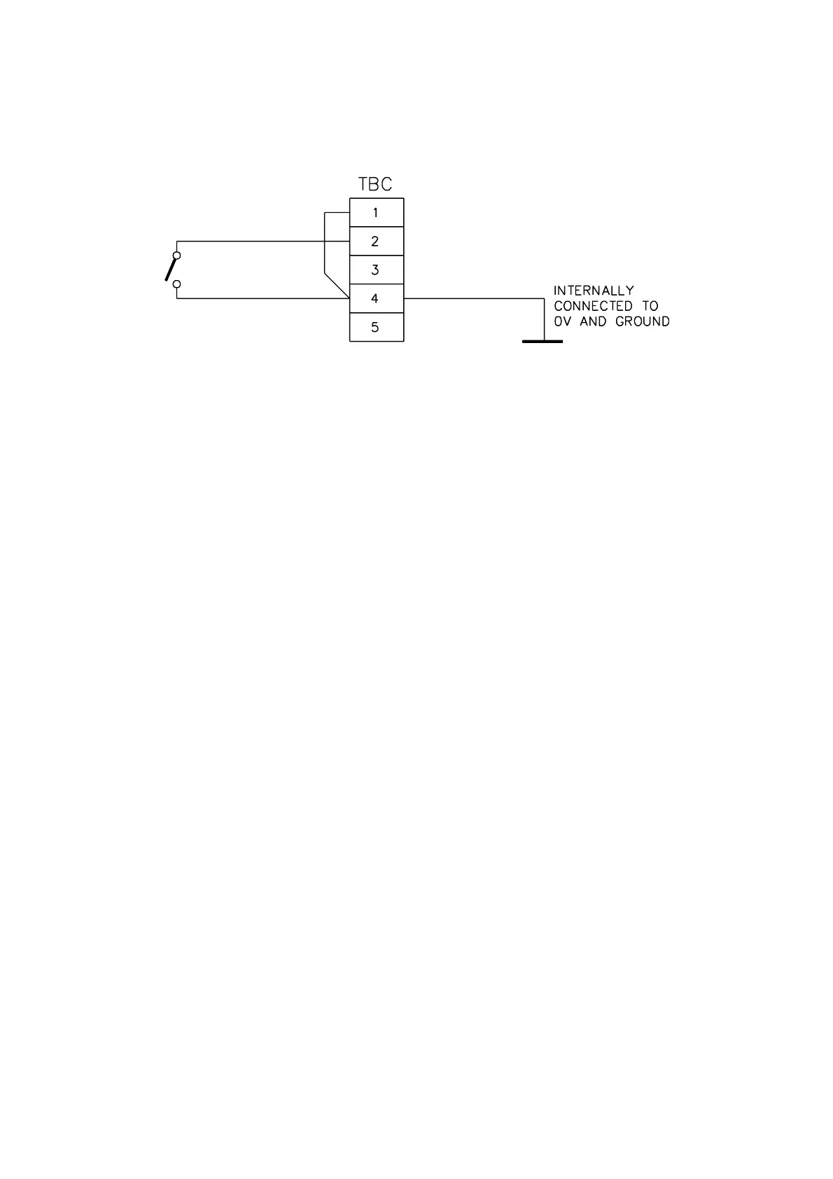
Electrical connection for an initiation by electrical contact is made to TB-C on board
01100916A. See Figure 2.17.
Figure 2.17 Remote Initiation of Auto-calibration
Make connection to terminal 2 and to terminal 4. There may be a wire connecting 1 and 4.
This should not be removed.
The cable must be a screened, twisted pair, not exceeding 3 metres in length and having the
screen terminated within the 1101 or 1102 enclosure. Screen termination connections must be
kept as short as practical (less than 40mm). The recommended conductor size is 16/0.2mm
(20 AWG) or greater, since a smaller conductor may not be adequately clamped by the screw
terminals.
This cable must not be installed close to other cables or equipment likely to generate severe
levels of electro-magnetic interference.
Momentarily closing the contact will start auto-calibration.
2.12 FLOW ALARM
The output from the optional flow alarm on the 1161 dry gas sampling system may either be
taken to the 1100A system or to a separate annunciator.
Connections are made to the connector block (upper level) inside the flow alarm enclosure.
Electrical power connections are made to terminals 1, 3, and 5.
Signal connections are made to terminals 10 and 11. The logic is that when there is
insufficient sample gas flow the contacts open. They also open when the flow alarm unit loses
electrical power.
If the signal is to be used by the 1100A then connection is made to TB-C, terminals 1 and 4 on
the 01100916A board. Remove and discard the shorting link on these terminals. This is in the
Control unit (or Interface unit when this is used). Connections should be made with screened
cable.