26
Operating Instructions – MOVIFIT® basic
5
Motor connection
Electrical installation
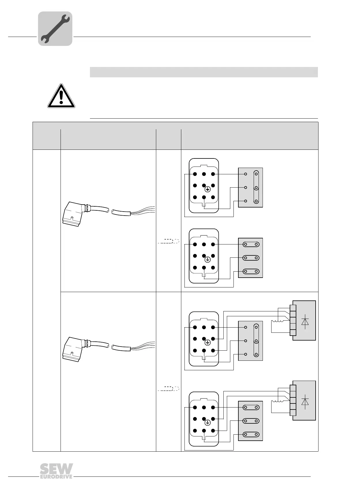
Connection cable The following table shows possible motor cables:
NOTICE
Danger in case of incorrect wiring of U1, V1, and W1 or short circuit. The motor outputs
of MOVIFIT
®
basic are not protected against short circuits.
Irreparable damage to the MOVIFIT
®
basic unit.
• Observe the following wiring diagrams.
• Prevent any short circuits between the conductors.
Connection cable and component
MOVIFIT
®
basic
Motor cable
Length/
Installa-
tion type
Motor connection
MOVIFIT
®
basic
inverter
Cable design: 4G2.5, shielded Max.
10 m
Motor without brake,
댴 connection
Motor without brake,
쑶 connection
Cable design: 4G2.5, unshielded
Part number: 1 814 874 3
Max. 3 m
Q 8/0 Open
Cable design: 7G2.5, shielded
Max.
10 m
Motor with brake,
댴 connection
Motor with brake,
쑶 connection
Cable design: 7G2.5, unshielded
Part number: 1 814 992 8
Max. 3 m
Q 8/0 Open
123
45
678
W2
U2
V2
U1
V1
W1
RD
BU
WH
BG
1
2
3
4
5
123
45
678
W2
U2
V2
U1
V1
W1
RD
BU
WH
BG
1
2
3
4
5