Operating Instructions – MOVIFIT® basic
43
6
Parameterization with LT-BG keypad
Startup
6.6.2 Parameterization
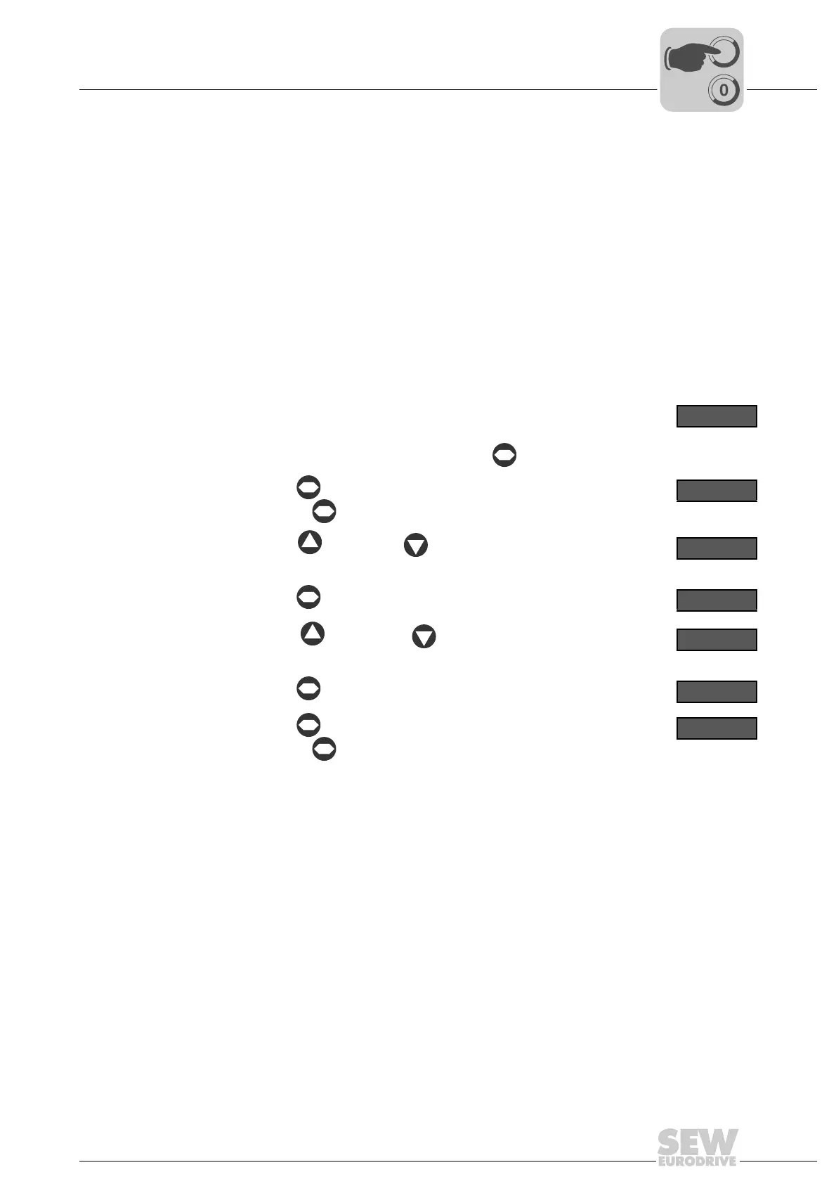
Proceed as follows to change the parameter values:
For a description of the parameters, refer to chapter "Parameter list – MOVIFIT
®
basic
inverter"
1. Check the connection of the MOVIFIT
®
basic unit.
See chapter "Electrical Installation".
2. Connect the LT-BG operator terminal to the MOVIFIT
®
basic unit.
See chapter "Connecting the operator terminals LT-BG and MB-LC" (page 33)
3. Make sure that the motor cannot start
e.g. by unplugging the motor connector(s) from the MOVIFIT
®
basic unit.
4.
Switch on the line voltage.
After initialization, the operator terminal shows the rotational fre-
quency "H", the output current "A", or the motor power "P".
To change the display, briefly press the key.
H 50.0
5.
Use the key to activate the parameter mode.
(Press the key for more than 1 s)
P 1 - 0 1
6.
Use the key and the key to select the desired parameter.
P 1 - 0 3
7.
Use the key to activate the setting mode.
5.0
8.
Use the key and the key to set the required parameter
value.
2.0
9.
Use the key to quit the setting mode.
P 1 - 0 3
10.
Use the key to quit the parameter mode.
(Press the key for more than 1 s)
The operator terminal shows "StoP", "H ", "A ", or "P ".
S t o P
11. Switch off the line voltage.
12. Plug in the motor connector(s) at the MOVIFIT
®
basic unit.
13. NOTICE Damage due to missing or incorrectly mounted screw plug of the diagnos-
tics interface X50. The degree of protection of MOVIFIT
®
basic specified in chapter
"Technical data" only applies if the screw plug of the diagnostic interface is mounted
correctly.
Damage to the MOVIFIT
®
basic unit.
• Once you have finished working with the operator terminal, unplug the connector
from the diagnostics interface.
• Screw the screw plug of the diagnostics interface back in with the seal.