Operating Instructions Chapter 8
C4000 Palletizer Std./Adv.
C4000 Fusion
8012249/YT69/2016-02-25 © SICK AG • Industrial Safety Systems • Germany • All rights reserved 85
Subject to change without notice
Commissioning
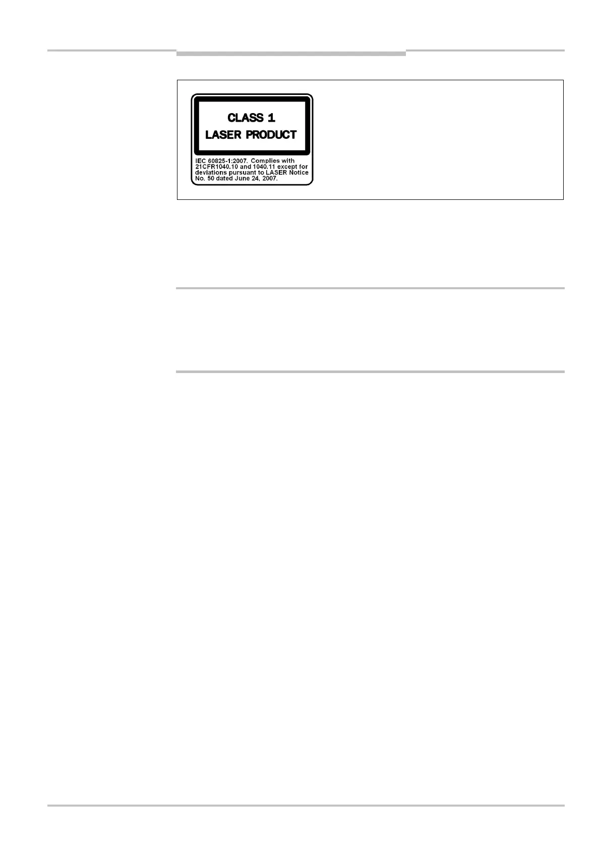
The laser alignment aid for the C4000 is classified as a
class 1 laser. Additional measures for screening the laser
radiation are not necessary.
The laser warning label is part of the information on the
type label on the rear of the C4000 Fusion sender
immediately above the system end cap.
This device complies with the standard CDRH 21 CFR 1040.10 as well as EN 60825E1.
There the following note is required: “Caution — use of controls or adjustments or perfor-
mance of procedures other than those specified herein may result in hazardous radiation
exposure!”
The laser is used to align the optics for a single sender and receiver pair.
Do not look into the laser outlet opening!
The laser alignment aid on the C4000 Fusion sender unit is classified as class 1 (safe for
the eyes) in accordance with the applicable standards. Nevertheless, as for any source
that radiates energy (e.g. light), extended direct action by the laser light may damage your
sight.
The laser alignment aid in conjunction with the indications on the 7Esegment display en-
ables you to precisely adjust and align the C4000 Fusion. The laser alignment aid must be
activated manually.
How to align the C4000 Fusion with the aid of the integrated alignment aid:
Check with a spirit level whether the devices are mounted vertically or horizontally.
Check whether the following points are the same distance from the floor:
– first beam of the sender
– first beam of the receiver
Loosen the clamping bolts which hold sender and receiver in place.
Activate the laser alignment aid by placing a finger on the laser in the sender.
Rotate the sender until the alignment beam is incident in the centre of the receiver.
Watch the alignment information on the 7E segment display of the receiver. The optimal
alignment of the beam near the 7Esegment display is achieved when or appears on
the 7Esegment display.
Then fix sender and receiver.
8.3 Test notes
Check the protective device as described below and in accordance with the applicable
standards and regulations.
These tests are also used to identify if the protection is affected by external light sources
or other unusual ambient effects.
These tests must therefore always be performed.
Note
WARNING

 Loading...


