Chapter 7 Operating Instructions
C4000 Palletizer Std./Adv.
C4000 Fusion
74 © SICK AG • Industrial Safety Systems • Germany • All rights reserved 8012249/YT69/2016-02-25
Subject to change without notice
Electrical installation
The C4000 safety light curtain meets the interference suppression requirements (EMC)
for industrial use (interference suppression class A). When used in residential areas it
can cause interference.
To ensure full electromagnetic compatibility (EMC), functional earth (FE) must be
connected.
To meet the requirements of the relevant product standards (e.g. IEC 61496E1), the
external voltage supply for the devices (SELV) must be able to withstand a brief mains
failure of 20 ms as required by EN 60204E1. The power supply must provide safe mains
isolation (SELV/PELV) and have a current limit of max. 8 A. Suitable power supplies are
available as accessories from SICK (see section 13.5 “Accessories” on page 116).
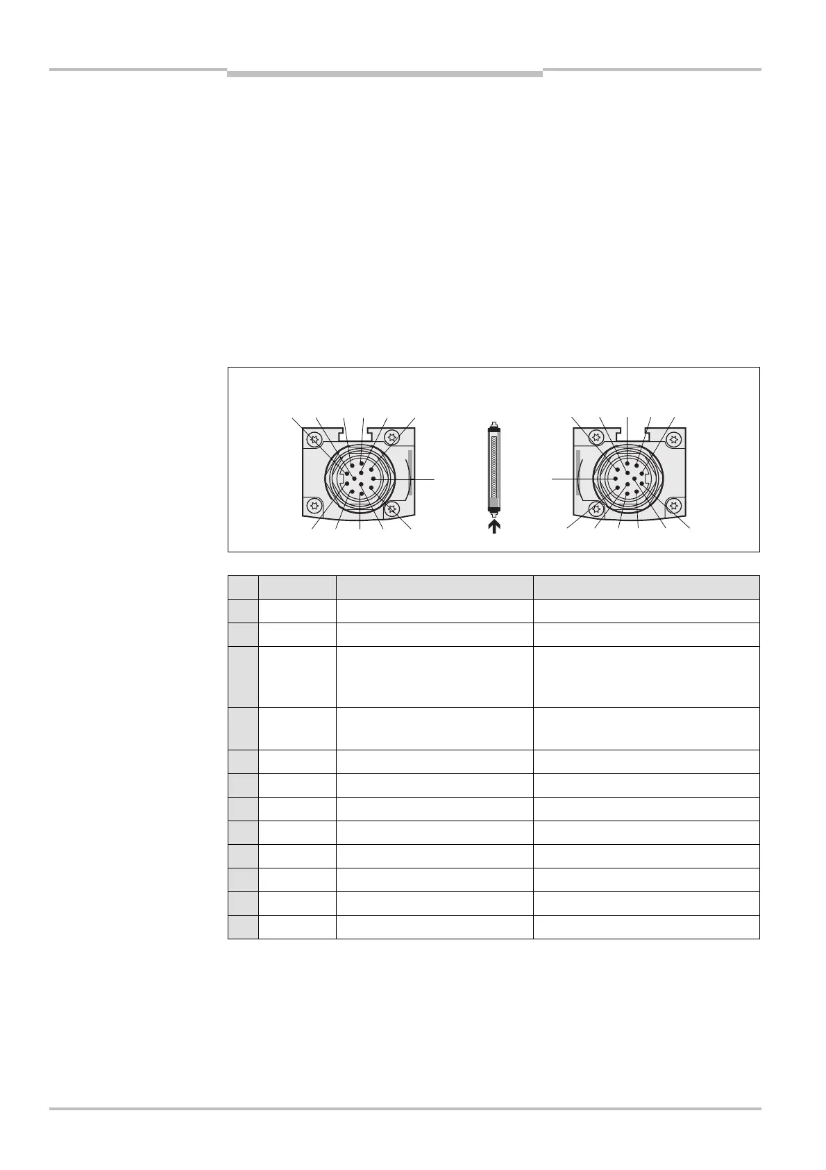
7.1 System connection M26× 11 + FE
Pin Wire colour Sender Receiver
1 Brown 24 V DC input (voltage supply) 24 V DC input (voltage supply)
2 Blue 0 V DC (voltage supply) 0 V DC (voltage supply)
3 Grey Test input:
0 V: external test active
24 V: external test inactive
OSSD1 (output signal switching
device 1)
4 Pink Reserved OSSD2 (output signal switching
device 2)
5 Red Reserved Reset/restart
6 Yellow Reserved External device monitoring (EDM)
7 White Reserved Application diagnostic output (ADO)
8 Red/blue Reserved Output Reset required
9 Black Device communication (EFI
A
) Device communication (EFI
A
)
10 Purple Device communication (EFI
B
) Device communication (EFI
B
)
11 Grey/pink Reserved Reserved
FE Green Functional earth Functional earth
For the connection of pin 9 and 10 only use cable with twisted cores, e.g. the SICK con-
nection cables available as accessories (see section 13.5 “Accessories” on page 116).
If you do not use either a SICK switching amplifier or a SICK bus node, to improve the
EMC behaviour we recommend the termination of the connections pin 9 and 10 (device
communication EFI) on the system connection in the control cabinet using a resistor of
182 (SICK part number 2027227).
Notes
system connection
M26
× 11 + FE
system connection
M26
× 11 + FE
Notes

 Loading...


