Chapter 7 Operating Instructions
C4000 Palletizer Std./Adv.
C4000 Fusion
76 © SICK AG • Industrial Safety Systems • Germany • All rights reserved 8012249/YT69/2016-02-25
Subject to change without notice
Electrical installation
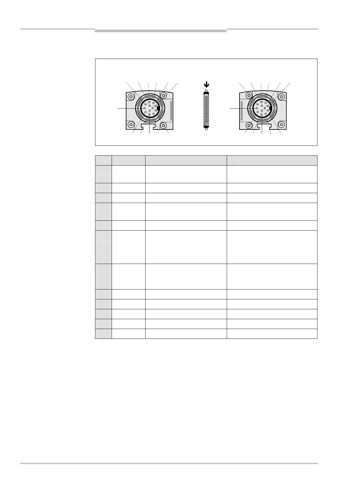
7.3 Extension connection M26× 11 + FE
Pin Wire colour Sender Receiver
1 Brown 24 V DC output (voltage
supply)
24 V DC output (voltage supply)
2 Blue 0 V DC (voltage supply) 0 V DC (voltage supply)
3 Grey Reserved Input emergency stop 1/bypass
4 Pink Reserved Input emergency
stop 2/bypass/teach-in
5 Red Reserved Reset/restart
6 Yellow Reserved Test output emergency
stop 2/bypass/
output photoelectric
switch 2/teach-in
7 White Reserved Test output emergency
stop 1/bypass/
output photoelectric switch 1
8 Red/blue Reserved Output Reset required
9 Black Device communication (EFI
A
) Device communication (EFI
A
)
10 Purple Device communication (EFI
B
) Device communication (EFI
B
)
11 Grey/pink Reserved Reserved
FE Green Functional earth Functional earth
The plug alignment (rotational position) in the housing may vary from device to device.
You can identify the correct pin assignment by the position of the pins in relation to
each other as shown in the drawings.
If you do not connect any further safety light curtain to an extension connection, then
you must also not connect any cable to pins 9 and 10.
If the extension connection is no longer required, always screw the attached protective
cap over the extension connection.
extension connection
M26
× 11 + FE
extension connection
M26
× 11 + FE
Notes
 Loading...


