Product Description
GMS800 · Operating Instructions · 8013025 V1.2 · © SICK MAIHAK GmbH 19
Subject to change without notice
2.4 Module connection via CAN bus
Module data are transferred via a CANopen bus. Each module has an own name or module
number (bus address). The control unit or PC software “SOPAS ET” communicate with each
individual module.
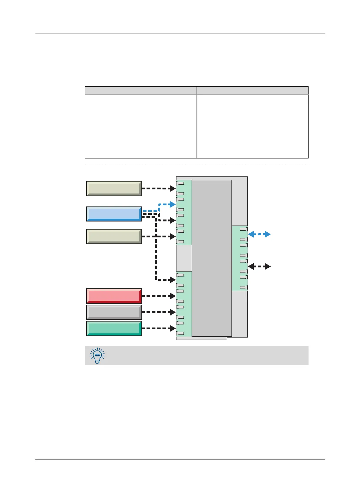
Fig. 4 Internal connections (schematic)
The Analyzer modules The control unit
● store their individual operating parame-
ters internally (e.g. operating hours)
● automatically send their current mea-
sured values to the control unit.
● generates a status message that classi-
fies the current measured value
● computes the measured values – as
required and with appropriate program-
ming (with other measured variable and
parameters)
● displays the measured values and
passes them to the outputs and inter-
faces.
Additional separator couplers must be fitted to the CAN bus when the modules
are installed physically separated (e.g. in system cabinets).
Gas module
Ext. LAN
Analyzer module
Analyzer module
Control unit
Analyzer module
I/O module
Ext. CAN bus
or
RS 485
Distribution board
(CAN bus)
 Loading...


