Operating Instructions GM35
Probe Model
Installation
8009389/07-2006 © SICK MAIHAK GmbH • Germany · All rights reserved 37
DANGER
Note the installed loads for the power supply.
The evaluation unit is configured for 230 V AC operation on delivery.
‡ For 115 or 120 V AC, attach the relevant jumper, as shown on the connection plate of
the evaluation unit.
‡ Ensure that the power supply has been installed in accordance with the specifications
(see Connections on the evaluation unit) and is disconnected from power.
‡ Route the signal cable for the inputs and outputs through the screwed connections at the
bottom of the housing to the Evaluation Unit and connect it as shown in Fig. 18.
‡ If the customer supplied CAN cable is used connect wires to terminal block “Sensor”. In
this case +24 V and GND are not connected.
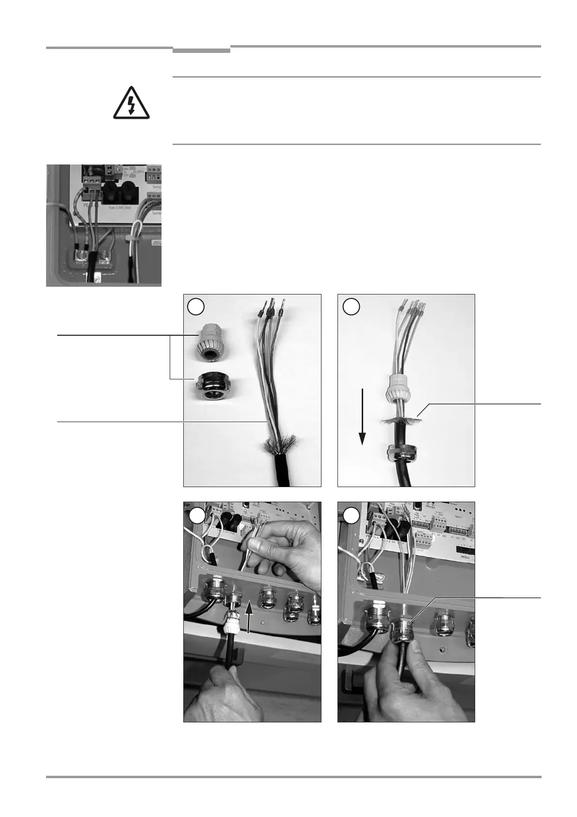
See step 1 to 4 below.
Fig. 19 Attaching the CAN bus cable to the Evaluation Unit
3 4
21
Shield for the
CAN cable
Conduit thread connection
for the Evaluation Unit
CAN bus cable
Conduit thread
connection
fitted to the
Evaluation Uni

 Loading...


