GM35 Operating Instructions
Probe Model
Installation
36 © SICK MAIHAK GmbH • Germany · All rights reserved 8009389/07-2006
4.4.3 Electrical connections for the evaluation unit
The procedure for laying the cables for the evaluation unit and the relevant specifications
are described in Chapter 3.4 "Preparations for electrical installation" and Fig. 10 "Cable
routing diagram", page 27.
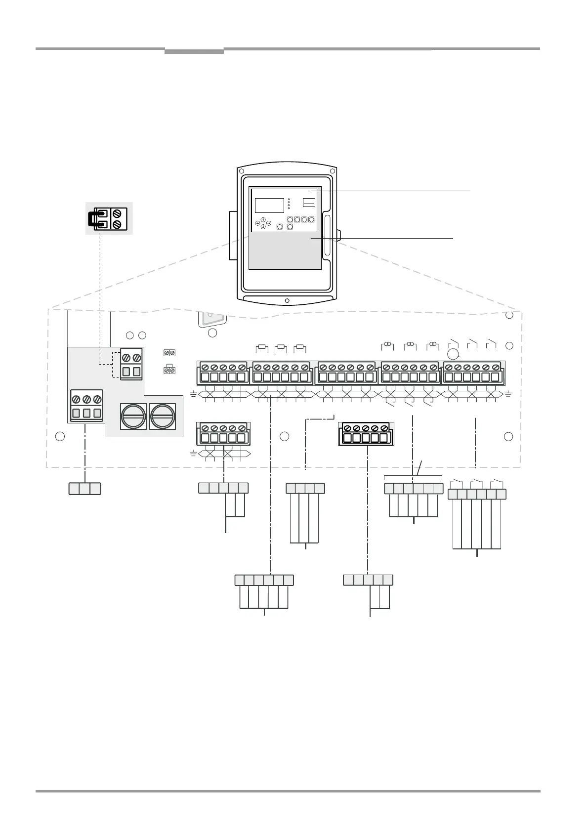
Fig. 18 Connections on the evaluation unit
‡ Open the housing door on the evaluation unit.
± ± ±
± ± ±
±
± ±
7,
5
3
7,53
=
>
/
5(
*
35
(
*
>
=
>
/
5(
*
35
(
*
>
)
)
9;:
=
.5+
=(*"
/a
_
3RZHU
99
3RZHU&$1
9
±+/*1'
'LJLWDOLQ
$QDORJLQ
P$
+]
9
RU
9
$2$2$2',',$,$,$,
6HQVRU
'2'2'2
'LJLWDORXW
$&'&99$$
$QDORJRXW
P$
6HQVRU
)XVH$79
3(1/
FRQWUDVW
;W]
,U[LY TLHZ
KPHN WHY JHS THPU[
6WLYH[PVU
:LY]PJL
>HYUPUN
4HSM\UJ[PVU
.4
,]HS\H[PVU<UP[
With a 115 V or 120 V voltage supply,
insert this jumper.
48 V AC/DC; 60 VA,
1 A (6 x 0.75
2
)
relay outputs
PROFIBUS
0...20 mA (6 x
0.75
2
)
analog outputs
Cabling
(provided by
customer)
PROFIBUS (optional)
0...20 mA (6 x 0.5
2
)
analog inputs
Floating contact (6 x
0.75
2
) digital inputs
Fault
1)
Need for maint.
2)
Function control
2)
Check cycle
Autocal
(CAN H, L twisted, shielded)
GM35 SR unit or
terminal box
Free assignment
Control board
Connections board
Cast housing shown
1)
NC contact
2)
NO contact
 Loading...


