Operating Instructions GM35
Probe Model
Planning guidelines
8009389/07-2006 © SICK MAIHAK GmbH • Germany · All rights reserved 27
3.4.1 Signal and power supply cables
The relevant safety instructions, which include those in Chapter 2 of this manual, and gen-
eral safety regulations must be followed at all times. When conducting work on electrical
equipment, always disconnect the equipment from the power supply and ensure that the
power supply cannot be reconnected by third persons. The power supply must be discon-
nected for installing the devices.
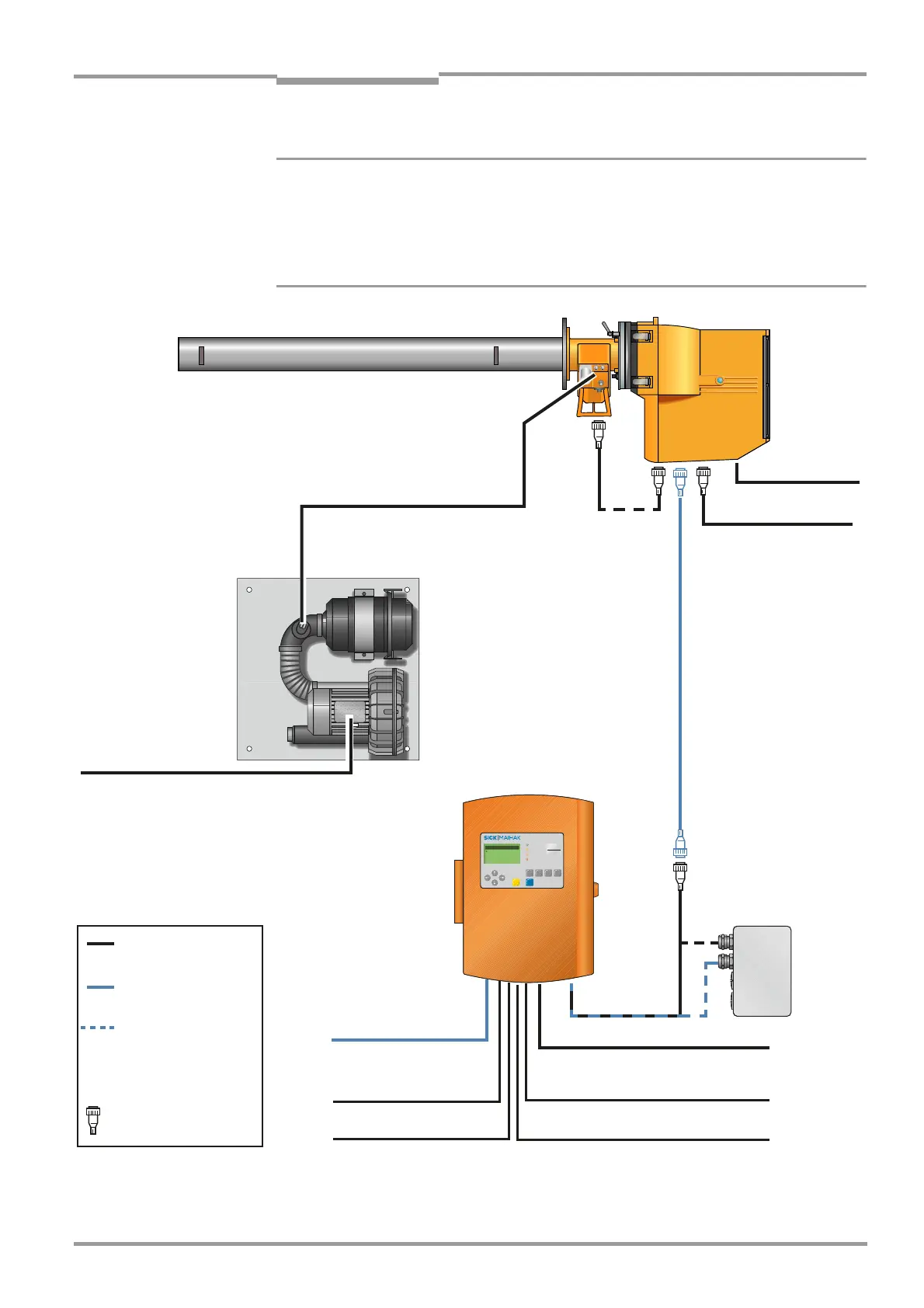
Fig. 10 Cable routing diagram
THPU[JHSWHYKPHN
.4
,]HS\H[PVU<UP[
&2
&2
+
2
PJ
P
5HIFRQGLWLRQV
+XPZHW
0HDVXULQJ
6WLYH[PVU
:LY]PJL
>HY UP U
4HSM\UJ[PVU
Power supply (230/
115 V AC) *
10 m, 3 x 1.5 mm
2
SR unit
Measuring probe (example: GMP)
CAN *
1 m
Evaluation Unit
CAN bus extension,
preassembled, 15 m
CAN bus cable
(standard), 2 m *
Terminal box (option)
Standard cable
connection
Optional cable
connection
Cables supplied
with system
*
Preassembled
with connector(s)
Purge-air unit SLV 4
(Standard for GMP
probe)
Power supply
4 x 1.5 mm
2
Signal cable for:
• Filter monitoring of the SLV 4 – 2 x 0.6 mm
2
,
on pressure monitor with flat pin bushing
6.3 x 0.8 mm
• Pressure connection
Functional ground
2.5 mm
2
Power supply (230/115 V AC)
3 x 0.75 mm
2
PROFIBUS 5 x 0.5 mm
2
3 binary inputs 6 x 0.5
mm
2
3 analog inputs 6 x 0.5 mm
2
3 binary outputs 6 x 0.5 mm
2
3 analog outputs 6 x 0.5 mm
2
For extending the CAN bus
connection with cable
provided by customer
(1 x 2 x 0.5 mm
2
, shielded
twisted pair)
Cable for optional
terminal box

 Loading...


