Operating Instructions GM35
Probe Model
Installation
8009389/07-2006 © SICK MAIHAK GmbH • Germany · All rights reserved 35
If the unit is mounted outdoors or in an unprotected environment:
‡ Protect the opening on the purge air hose against moisture and dirt until the measuring
system is commissioned; if necessary, reattach the seal you removed earlier.
‡ Mount the weatherproof cover
4.4.2 CAN bus wiring options
As discussed in the Chapter on project planning (see chapter 3.4, page 26 ), the following
options are available for the CAN bus connection between the SR unit and the evaluation
unit:
• Standard cable 4 m (13.1 ft), preassembled
• Standard cable 4 m (13.1 ft), as well as an additional, preassembled CAN bus extension
cable (15 m/49.2 ft)
• Terminal box with preassembled 4 m cable for connection to the SR unit; a cable must
be provided by the customer for connection to the evaluation unit.
For information on selecting a suitable connection type, see Options for CAN bus connec-
tion, Seite 22.
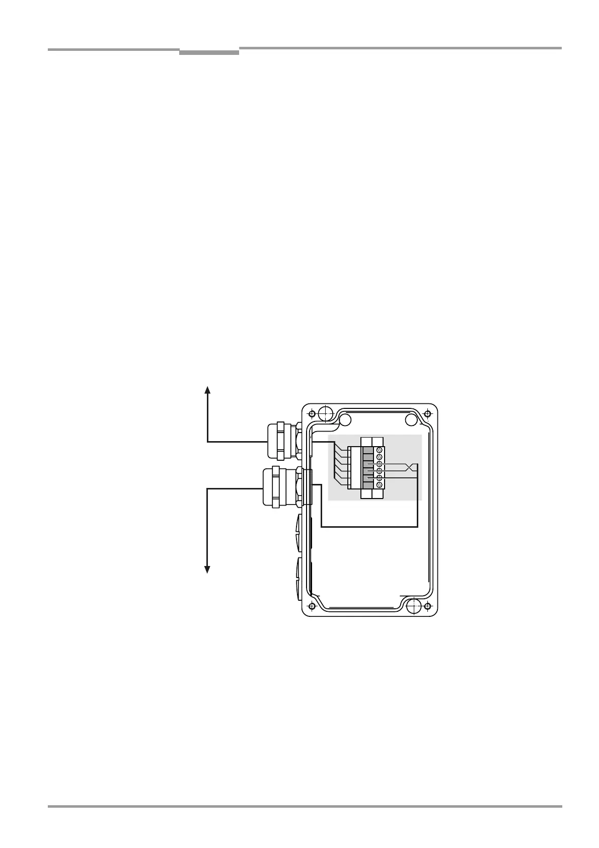
Connections in the terminal box
The terminals in the terminal box are connected as follows:
Fig. 17 Terminal box for CAN bus connection with a cable length greater than 19 m (62.3 ft)
between the SR unit and evaluation unit
‡ Route the CAN bus cable provided by the customer through the free screwed connection
to the terminal box.
‡ Connect the shield on the screwed connection to the housing of the terminal box.
‡ Connect the wires shown in Fig. 17 to the terminal strip; make sure that a twisted wire
pair is used for CAN-H and CAN-L.
WR
NY
`L
NU
IU
^O
*(5/
*(53
*(5.5+
Preassembled cable with
connector, 4 m,
to the SR unit
Cable to evaluation
unit (provided by
customer)
 Loading...


