Operating Instructions GM35
Probe Model
Handling the evaluation unit
8009389/07-2006 © SICK MAIHAK GmbH • Germany · All rights reserved 41
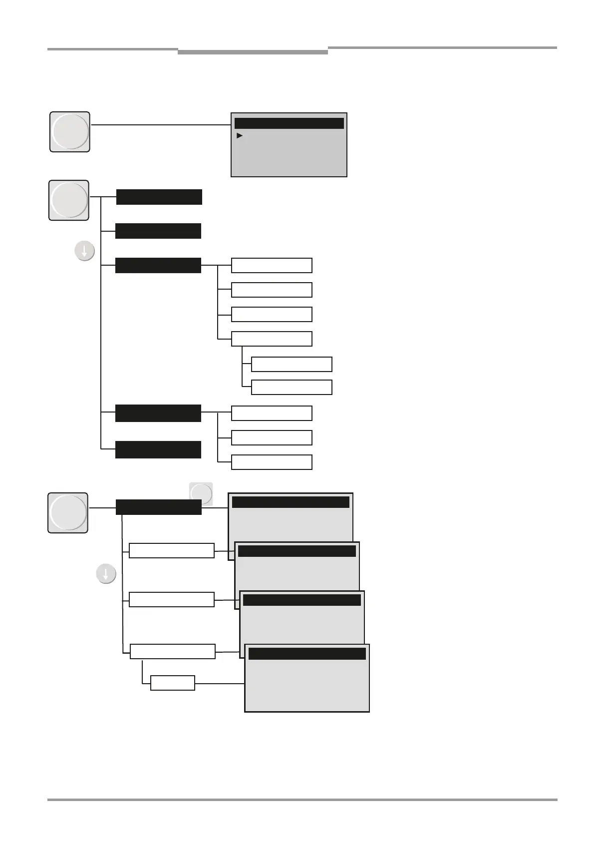
5.2.2 Menu Structure
Fig. 21 Menu structure of the GM35/part 1
meas
ppm
Measuring
CO
CO2
H2O
Ref. conditions
Hum: wet
Rohsignale CO
Rohsignale CO
diag
Malfunction
Warning
Sensor Values
Check values
GM 35 general
CO
H2O
Probe
CO
CO2
H2O
Show Opt. Align
Cross Duct OH
Cross Duct Refl
Measuring mode
Diagnosis
Plain-text messages:
see Seite 83
Plain-text messages:
see Seite 92
Current monitoring values of the sensors
(amplifier settings, internal temperature
controllers, and so on)
Cross-duct version:
• sender/receiver unit (OH)
• Reflector
Check values
Displays the optical alignment of the SR
unit and reflector in measuring mode.
Calibration
• Check cycle for test purposes,
for example, after maintenance
• Zero adjustment with ambient air
(e.g. during commissioning)
• Filter box measurement for
– Control filter (H
2
O channel, CO
2
for
high concentrations)
– Test gas (CO+15 vol% within CO
2
)
• Manual test (CO, CO
2
, H
2
O),
(e.g. with clean gas)
• Adjusts the device-internal pressure
and temperature measurement in
line with reference measurements.
Nullabgleich
← back
Nullabgleich
← back← back
Nullabgleich
Nullabgleich
Enter
cal
Check Cycle
Check cycle
Start Check cycle
Procedure successful
Zero Adjust
Zero Adjust CO
Box Measuring
Manual Test
Box Measuring
Manual Test ZERO
Zero gas
CO, CO2
Zero gas
CO: 3 ppm
CO2: 0.9 % Vol
H2O: 0.4 % Vol
Start Meas. Grid
Start Meas. Gas

 Loading...


