18
8012428/YWL2/3-0/2016-08| SICKO P E R A T I N G I N S T R U C T I O N S | DUSTHUNTER T
Subject to change without notice
2 PRODUCT DESCRIPTION
Data transfer to and power supply (24 V DC) from the MCU control unit run via a shielded
line with 4 wires and plug connector. An RS485 interface is available for service purposes.
Clean air to cool the probe and keep the optical surfaces clean is fed via a purge air con-
nection.
The sender/receiver unit is fastened to the duct with a flange with tube (see “Device com-
ponents”, page 16).
The alignment of the optical axes as well as the current device state (operation = green
LED, failure = red LED, maintenance request = yellow LED; see “Sender/receiver unit DHT-
Txx”, page 17) are shown at the control window.
On DUSTHUNTER T100/T200, the enclosure with fitted sender/receiver unit can be
swiveled to the side after the knurled screws have been loosened. Optics, electronics and
mechanical components can then be easily accessed for maintenance work.
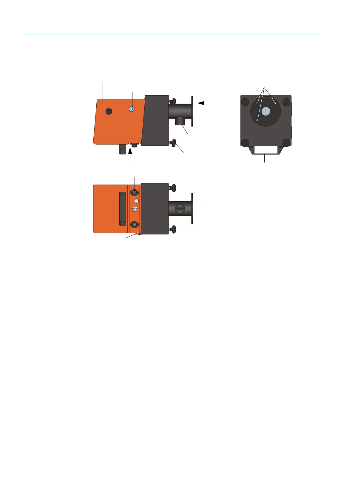
Sender/receiver unit for DUSTHUNTER T100/200
10
A
A
B
B
Enclosure with electronics (swivel-
mounted)
Connection for connection cable to MCU
Control window
Hinge
Mounting holes
Connection for connection cable to reflector
(only DUSTHUNTER T200)
Handle
Knurled screw
Flange Purge air connection
 Loading...


