66
8012428/YWL2/3-0/2016-08| SICKO P E R A T I N G I N S T R U C T I O N S | DUSTHUNTER T
Subject to change without notice
4 START-UP AND PARAMETER SETTINGS
▸ For DUSTHUNTER T200, click “Mechanical centring” (‚Step 1‘) in the “Adjustment /
Manual Adjustment / Transmission set reference” directory (see “SOPAS ET menu: DH
T100/Adjustment/Manual Adjustment/Transmission set reference”, page 64).
▸ Align the optical axes of the sender/receiver unit and reflector to each other.
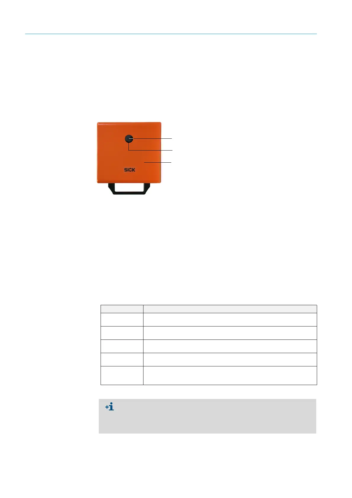
Align the sender/receiver unit so that the sender spot lies on the middle of the opening
for the reflector (see “Reflector”, page 20). Align the reflector so that sender spot (1) can
be seen in the circular marking in the middle of the control window (2) on the back of the
enclosure (3).
Fig. 42: Sender spot on the back of the enclosure of the reflector
▸ Deactivate “Permanent LED light” checkbox (see “SOPAS ET menu: DH T100/
Adjustment/Manual Adjustment/Transmission set reference”, page 64).
▸ Check the alignment.
The optical axes are aligned exactly when:
– the green LED in the 4-quadrant display in the control window of the sender/receiver
unit lights (see “Focussing the sender light beam”, page 65)
– for DUSTHUNTER T100/T200, in the “Adjustment / Manual Adjustment / Trans-
mission set reference” directory (see “SOPAS ET menu: DH T100/Adjustment/
Manual Adjustment/Transmission set reference”, page 64, see “SOPAS ET menu: DH
T200/Adjustment/Manual Adjustment/Transmission set reference”, page 68), the
sender spot (black circular area in the “Show justification” window) is inside the green
circle.
A non-exact alignment
is signaled by lighting of the LED in the 4-quadrant display in the
control window in the following manner
:
Sender spot
Control window
Back of enclosure
LED lights Misalignment of the light spot on the reflector
Green and yellow Deviation max. approx. 0.1 ° in the shown direction; measured values are
valid
Yellow Deviation max. approx. 0.1 to 0.3 ° in the shown direction; measured values
are valid
Yellow and red Deviation approx. 0.3 ° to 0.4 ° in the shown direction; measured values are
valid; possibly larger swivel error than listed in the technical data
Red Deviation approx. 0.4 ° in the shown direction; measured values are valid;
possibly larger swivel error than listed in the technical data
Red LED lights as
a circle
Deviation > approx. 0.5 °or transmission < approx. 10%; dust concentration
too high or measuring system incorrectly scaled, self-alignment of
DUSTHUNTER T200 no longer possible
On the DUSTHUNTER T200, only rough alignment is necessary because the equip-
ment is fitted with an internal self-alignment. Click the “Optical centering” button in
the “Adjustment / Manual Adjustment / Transmission set reference” directory to
start automatic fine adjustment (see “SOPAS ET menu: DH T200/Adjustment/Man-
ual Adjustment/Transmission set reference”, page 68).
 Loading...


