72
8012428/YWL2/3-0/2016-08| SICKO P E R A T I N G I N S T R U C T I O N S | DUSTHUNTER T
Subject to change without notice
4 START-UP AND PARAMETER SETTINGS
▸ Connect connection line MCU - sender/receiver unit and screw tight; for DUSTHUNTER
T200 additionally the line for the connection of sender/receiver unit and reflector (see
“Sender/receiver unit DHT-Txx”, page 17, see “Reflector”, page 20).
▸ Align optical axis of sender/receiver unit by successive loosening of the self-locking nuts
for horizontal and vertical alignment on reflector.
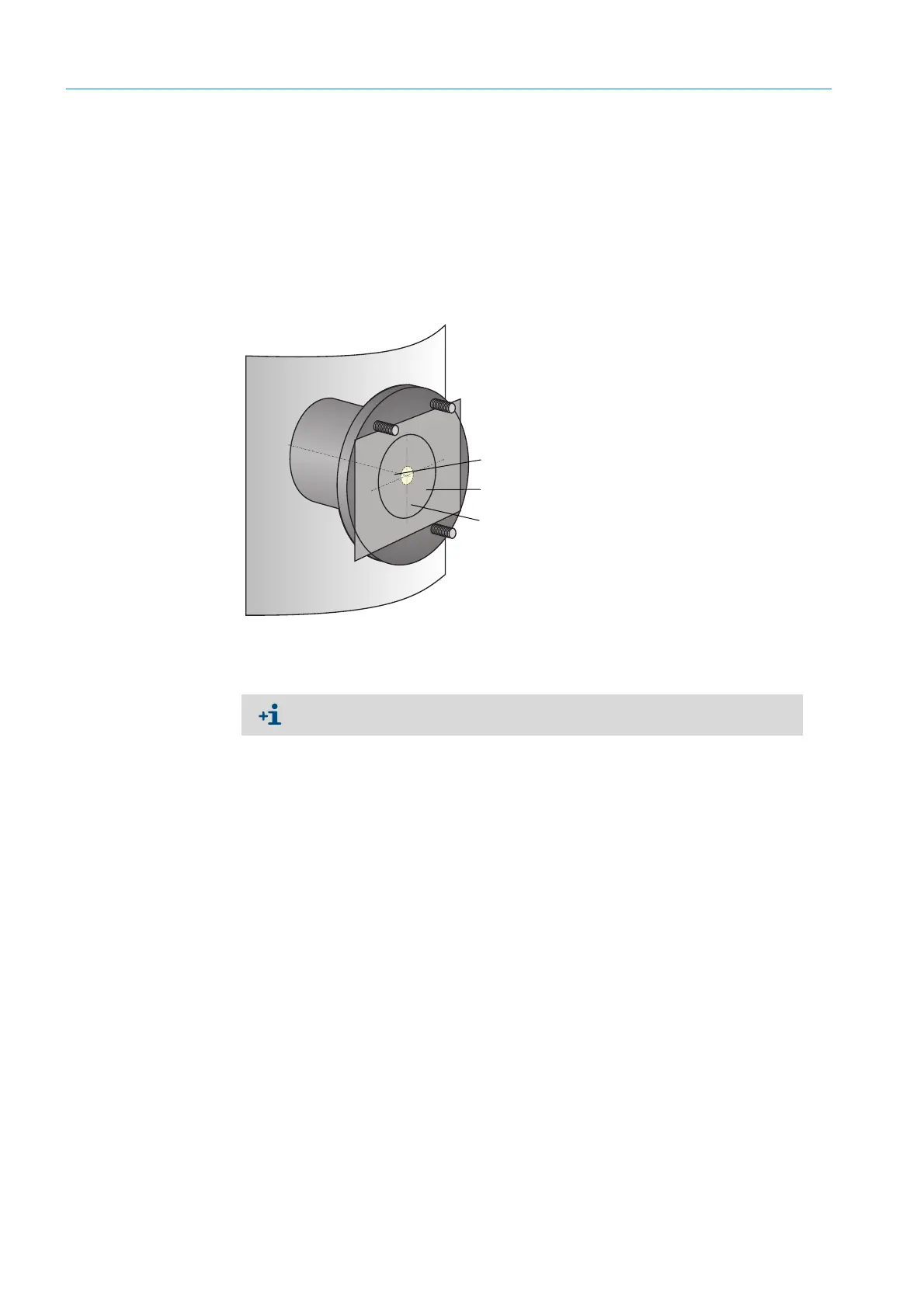
Alignment is correct when sender spot (1):
– on DUSTHUNTER T50, is on a semi-transparent foil (2) (possibly also white sheet of
paper) in the center of the flange tube of the reflector flange (3);
Fig. 47: Sender spot on reflector side (DUSTHUNTER T50)
– On DUSTHUNTER T100/T200 located in the center of the control window on the
enclosure rear of the reflector (see “Sender spot on the back of the enclosure of the
reflector”, page 66).
Sender spot
Semi-transparent foil
Flange tube
On DUSTHUNTER T200, the control window on the rear of the reflector is lit for bet-
ter inspection of the optical alignment in the “Maintenance” mode.
 Loading...


