FC_IN 8-pin
Male connector Pin Signal Meaning Color
1)
1 VDC 24 V supply voltage White
2 VDC 24 V supply voltage Brown
3 FC_A1 Test input 1 Green
4 FC_A2 Safe output 1 Yellow
5 GND GND supply voltage Gray
6 GND GND supply voltage Pink
7 FC_B1 Test input 2 Blue
8 FC_B2 Safe output 2 Red
Table 18: Pin assignment FC_IN 8-pin (male connector)
1)
The stated colors apply on the usage of pre-assembled cables (should be checked).
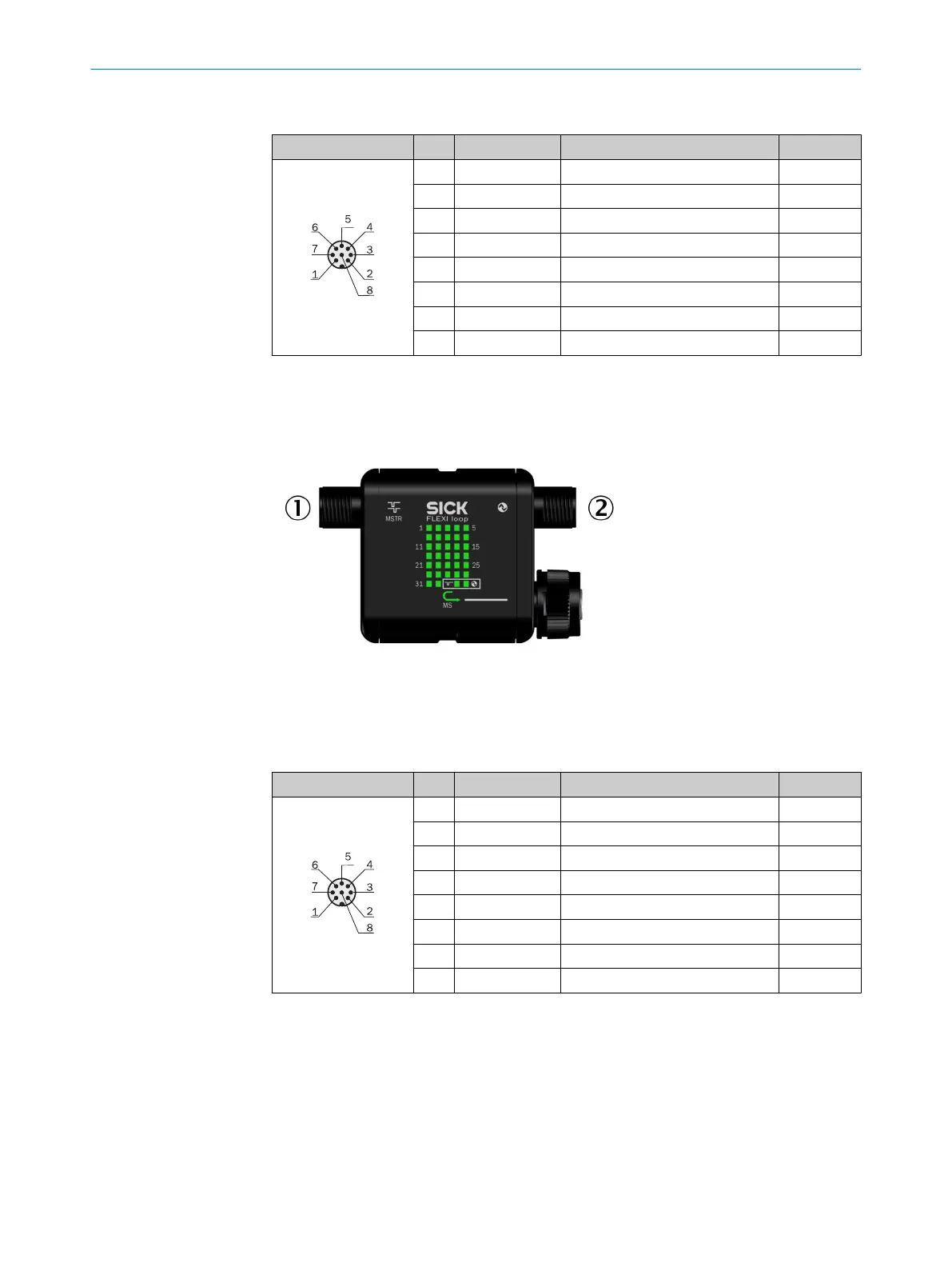
6.2.9 Connections of the MSTR2 Flexi Loop accessory
Figure 51: Connections of the MSTR2 Flexi Loop accessory
1
FC_IN (male connector)
2
IO-Link or AUX_IN/AUX_OUT (male connector)
FC_IN 8-pin
Male connector Pin Signal Meaning Color
1)
1 VDC 24 V supply voltage White
2 VDC 24 V supply voltage Brown
3 FC_A1 Test input 1 Green
4 FC_A2 Safe output 1 Yellow
5 GND GND supply voltage Gray
6 GND GND supply voltage Pink
7 FC_B1 Test input 2 Blue
8 FC_B2 Safe output 2 Red
Table 19: Pin assignment FC_IN 8-pin (male connector)
1)
The stated colors apply on the usage of pre-assembled cables (should be checked).
ELECTRICAL INSTALLATION 6
8015836/YT10/2016-05-24 | SICK O P E R A T I N G I N S T R U C T I O N S | Flexi Loop
49
Subject to change without notice