°
s
tatic errors
°
number of Flexi Loop nodes
MSTR2 Flexi Loop accessory and Flexi Loop node
b
Open t
he View Config Data branch.
✓
The View MSTR settings branch indicates the expected configuration for the MSTR2
Flexi Loop accessory.
✓
The View configuration data [n] branches indicate the expected configuration for all
Flexi Loop node positions. They also indicate information on the Flexi Loop node
actually found at this position.
°
type code of the Flexi Loop node configured
°
all parameters configured
°
type code of the Flexi Loop node detected
°
manufacturer
°
software version
°
serial number
°
Node voltage if this has been read in with a command (see "Standard com‐
mands", page 64)
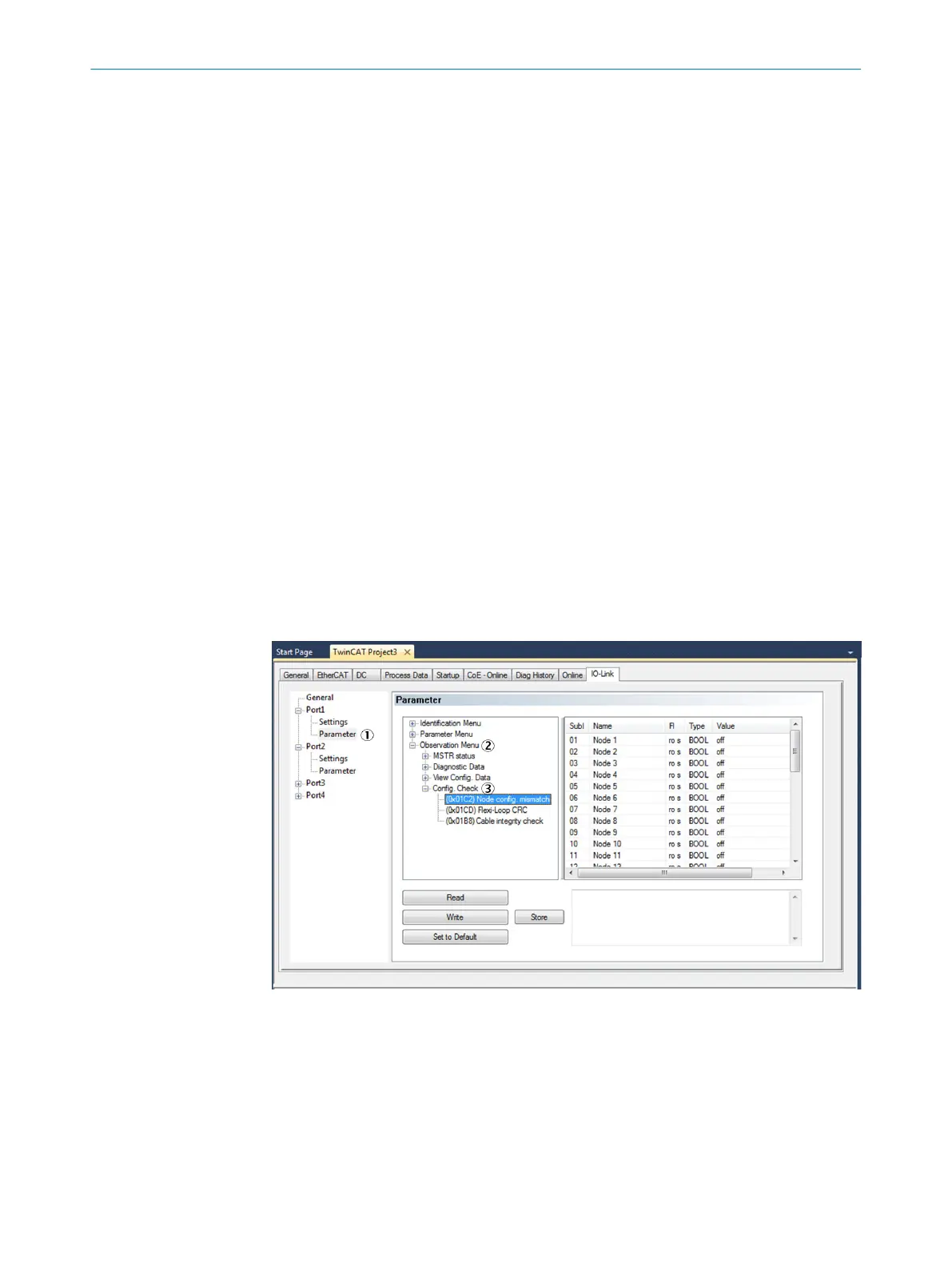
9.4.2 Test tools for the configuration
You can use the PLC to read information out from the Flexi Loop MSTR2 accessory.
b
Login t
o the configuration software for the standard controller as Observer.
b
Change to Parameter on the IO-Link port used.
b
Change to Observation Menu in the command tree.
b
Open the Config. Check branch.
✓
Test operations for the configuration are displayed.
Figure 68: Test operations for the configuration
1
Parameter
2
Observation Menu
3
Config. Check
Config Error
Open an o
verview of incorrectly configured Flexi Loop nodes using the Node config. mis‐
match command.
TROUBLESHOOTING 9
8015836/YT10/2016-05-24 | SICK O P E R A T I N G I N S T R U C T I O N S | Flexi Loop
79
Subject to change without notice