IO-Link 5-pin
Male connector Pin Signal Meaning Color
1)
1 VDC 24 V IO-Link supply voltage
2)
Brown
2 AUX_IN Non-safe input White
3 GND GND supply voltage Blue
4 C/Q or
A
UX_OUT
IO-Link interface/non-safe output Black
5 NC Not connected Gray
Table 20: Pin assignment for IO-Link or AUX_IN / AUX_OUT 5-pin (male connector)
1)
The stated colors apply on the usage of pre-assembled cables (should be checked).
2)
IO-Link and Flexi Loop must have separate supply voltages.
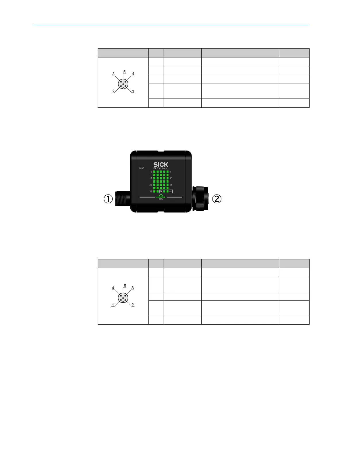
6.2.10 Connections of the DIAG Flexi Loop accessory
Figure 52: Connections of the DIAG Flexi Loop accessory
1
FL_IN (male connector)
2
FL_OUT (female connector)
FL_IN 5-pin
Male connector Pin Signal Meaning Color
1)
1 VDC 24 V supply voltage Brown
2 DATA_OUT Output to the Flexi Soft input In
+ 1
White
3 GND GND supply voltage Blue
4 SAFE_OUT Safe shutdown signal
Output t
o the Flexi Soft input In
Black
5 DATA_IN Input from the Flexi Soft output Xn Gray
Table 21: Pin assignment FL_IN (male connector)
1)
The stated colors apply on the usage of pre-assembled cables (should be checked).
6.2.11 Connection of Flexi Loop YCON1 and YCON2 adapters
The Flexi Loop YCON1 and YCON2 adapters are used to decouple the non-safe inputs
and outputs of t
he Flexi Loop EMSS8 or OSSD8 nodes.
6 ELECTRIC
AL INSTALLATION
50
O P E R A T I N G I N S T R U C T I O N S | Flexi Loop 8015836/YT10/2016-05-24 | SICK
Subject to change without notice