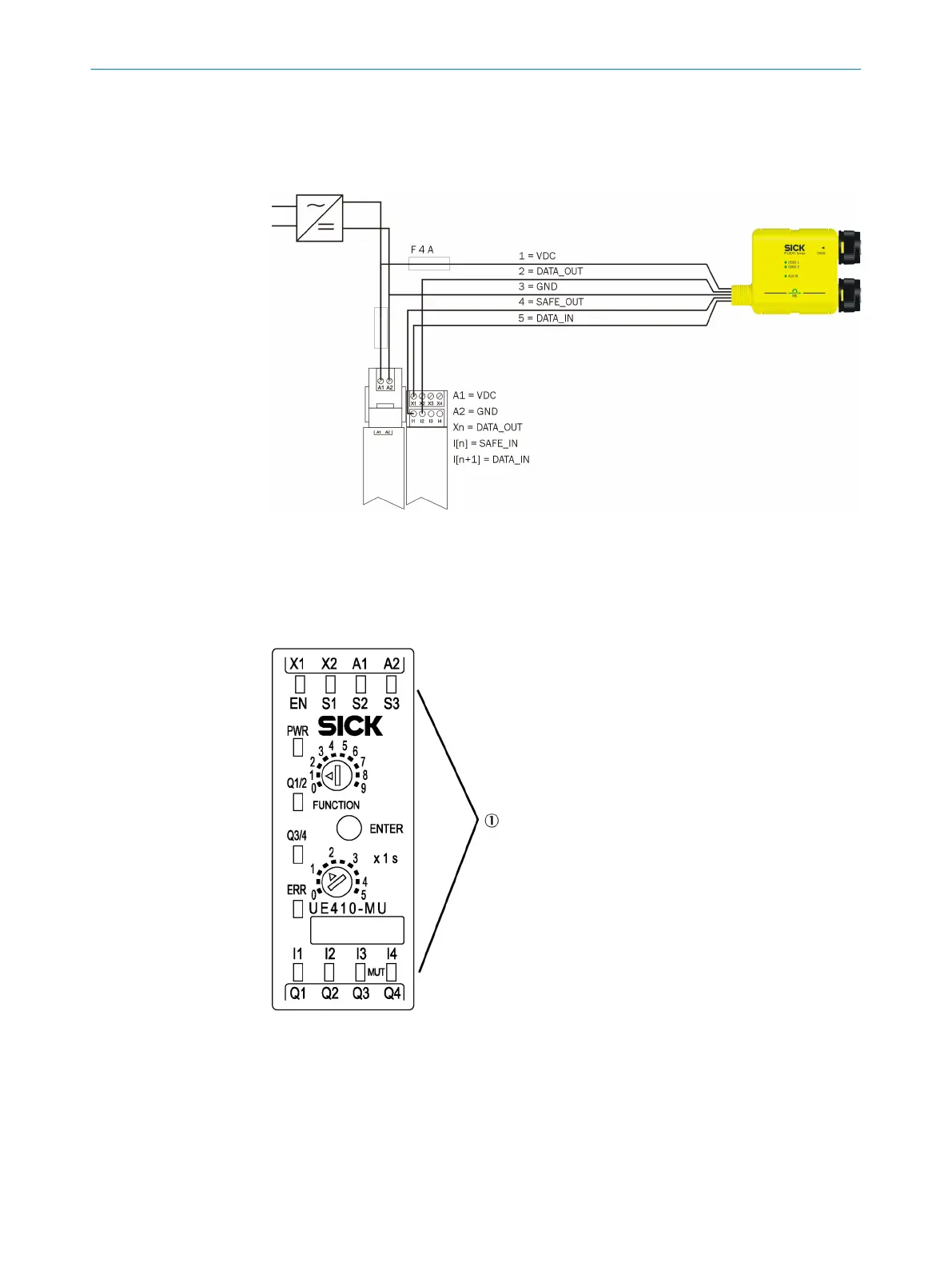
The safe sensor cascade is connected to one output (X) and two safe inputs (I) of an
I/O module.
The saf
e sensor cascade can be connected to the same voltage supply as the safety
controller. However, the current must be limited to 4 A.
Figure 41: Connection to Flexi Soft
Use 5-pin cables wit
h M12 female connector and open cable ends to connect the safe
sensor cascade (see "Pre-assembled cables", page 95).
6.2.2 Connection to Flexi Classic
Figure 42: Terminals on the Flexi Classic main module
1
Terminals for inputs and outputs
The figure shows the terminals for inputs and outputs based on the example of the
UE410-MU main module. The t
erminal pin assignments are listed in the “Flexi Classic
Modular Safety Controller” operating instructions.
ELECTRICAL INSTALLATION 6
8015836/YT10/2016-05-24 | SICK O P E R A T I N G I N S T R U C T I O N S | Flexi Loop
43
Subject to change without notice