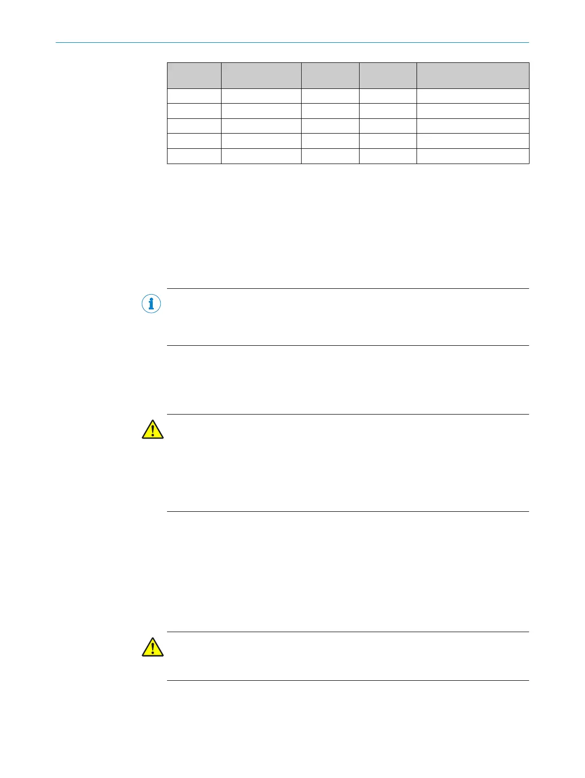
Segment Wire cross-section
[mm²]
Cable length
[m]
VoltageVDC
[V]
Current consumption of
connect
ed devices [A]
1 0.75 15.00 23.84 0.50
2 0.75 15.00 22.37 1.50
…
9 0.75 15.00 20.82 0.00
10 0.75 15.00 20.76 0.00
Table 10: Example voltage drop at 10 Flexi Loop nodes with wire cross-section 0.75 mm²
4.2.2 Possible solutions
If the voltage drop over a Flexi Loop segment or Flexi Loop section is too high, i.e. there
is an e
xcessively low input voltage at a node, then …
•
increase the wire cross-section.
•
if possible shorten the cables.
•
install the PWRI power supply accessory.
NOTE
Fle
xi Soft Designer supports an option for the offline calculation or online measuring of
the voltage drop (see the “Flexi Loop in the Flexi Soft Designer” operating instructions,
part no. 8014522).
If you require additional information and support during planning, please contact your
local SIC
K subsidiary.
4.3 Supply of OSSD devices
DANGER
Alw
ays supply the OSSD devices connected with power via the OSSD female connector
on the Flexi Loop node!
Never supply an OSSD device connected with power directly from a separate power sup‐
ply. If several power supplies in a Flexi Loop section are connected in parallel, in case of
a ground fault overcurrent and a cable fire may occur.
Always use the power supply accessory to connect additional power supplies.
4.4 Integration in the electrical control
4.4.1 Implementation of reset
Reset with the Flexi Soft safety controller
The r
eset function must be implemented in the Flexi Soft Designer logic editor (see the
“Flexi Loop in the Flexi Soft Designer” operating instructions, part no. 8014522). Pro‐
ceed as follows when connecting the reset buttons:
DANGER
b
Connect t
he control switch for restarting to a separate input. This input must not
be located on the same safe sensor cascade as the input for the reset button!
4 DESIGN
34
O P E R A T I N G I N S T R U C T I O N S | Flexi Loop 8015836/YT10/2016-05-24 | SICK
Subject to change without notice