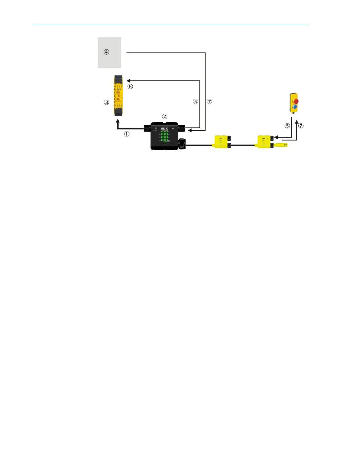
Figure 32: Reset with the Flexi Classic safety controller
1
Safe cut-off path
2
MSTR2 Flexi Loop accessory
3
Flexi Classic safety controller
4
Application (e.g. in a PLC)
5
Reset signal
6
Reset with Flexi Classic
7
Operation of the lamps
Signal propagation times via the Flexi-Loop communication always result in longer
pulse durations during signal transmission. For this reason an input signal from the
non-safe input (AUX_IN) on a Flexi Loop node has a longer pulse duration on the output
(AUX_OUT) of the MSTR2 Flexi Loop accessory.
4.4.2 Implementation of a safety locking device
Connection to EMSS node
The saf
ety switching contacts of a spring-locked safety locking device are connected to
the EMSS connections of the Flexi Loop node. Guard position monitoring for the protec‐
tive device and the interlocking device must be implemented with the same switching
element. If output monitoring of the Flexi Loop node is deactivated, the actuator signal
for the lock can be connected at the AUX_IN input. The interlocking device for the safety
locking device is connected at the AUX_OUT output.
4 DESIGN
36
O P E R A T I N G I N S T R U C T I O N S | Flexi Loop 8015836/YT10/2016-05-24 | SICK
Subject to change without notice