FLA-YCON00001
Figure 19: Flexi Loop adapter FLA-YCON00001
The Fle
xi Loop YCON1 adapter is used to decouple the non-safe inputs and outputs of
the Flexi Loop EMSS8 node.
FLA-YCON00002
Figure 20: Flexi Loop adapter FLA-YCON00002
The Fle
xi Loop YCON2 adapter is used to decouple the non-safe inputs and outputs of
the Flexi Loop OSSD8 node.
3.3.4 Status indicators
The LEDs indicate the operating states of the Flexi Loop nodes.
F
or a detailed overview of the error messages see "Indications of the LEDs", page 69.
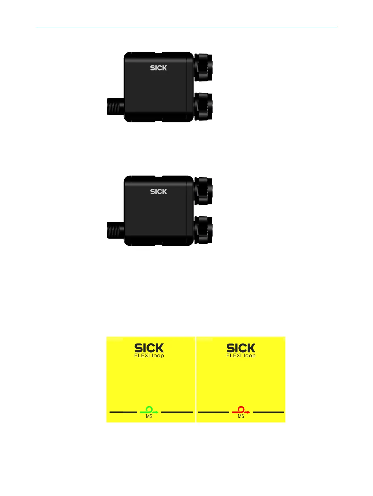
MS LED
Figure 21: MS LED
3 PR
ODUCT DESCRIPTION
24
O P E R A T I N G I N S T R U C T I O N S | Flexi Loop 8015836/YT10/2016-05-24 | SICK
Subject to change without notice