FL_IN 5-pin
Male connector Pin Signal Meaning Color
1)
1 VDC 24 V supply voltage Brown
2 DATA_OUT Output to the Flexi Soft input
In + 1
White
3 GND GND supply voltage Blue
4 SAFE_OUT Safe shutdown signal
Output t
o the Flexi Soft input In
Black
5 DATA_IN Input from the Flexi Soft output Xn Gray
Table 12: Pin assignment FL_IN (male connector)
1)
The stated colors apply on the usage of pre-assembled cables (should be checked).
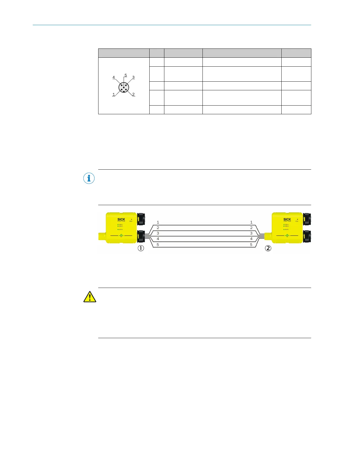
6.2.4 Connection of the Flexi Loop nodes
Within the safe sensor cascade the individual Flexi Loop nodes are connected using 1:1
cables (male/f
emale connector) via FL_OUT and FL_IN.
NOTE
b
Onl
y use cables with straight male or female connectors.
b
Never connect two Flexi Loop nodes directly by plugging the male connector of one
into the female connector of the other.
Figure 45: Connection FL_OUT to FL_IN
1
FL_OUT (female connector)
2
FL_IN (male connector)
DANGER
N
ever cut into the connection cables between the Flexi Loop nodes!
If the cables for the safe sensor cascade are cut into, e.g. to supply the cascade directly
using a separate power supply, then several power supplies will be connected in paral‐
lel.
This situation can result in overcurrent and a cable fire in case of a ground fault.
ELECTRICAL INSTALLATION 6
8015836/YT10/2016-05-24 | SICK O P E R A T I N G I N S T R U C T I O N S | Flexi Loop
45
Subject to change without notice