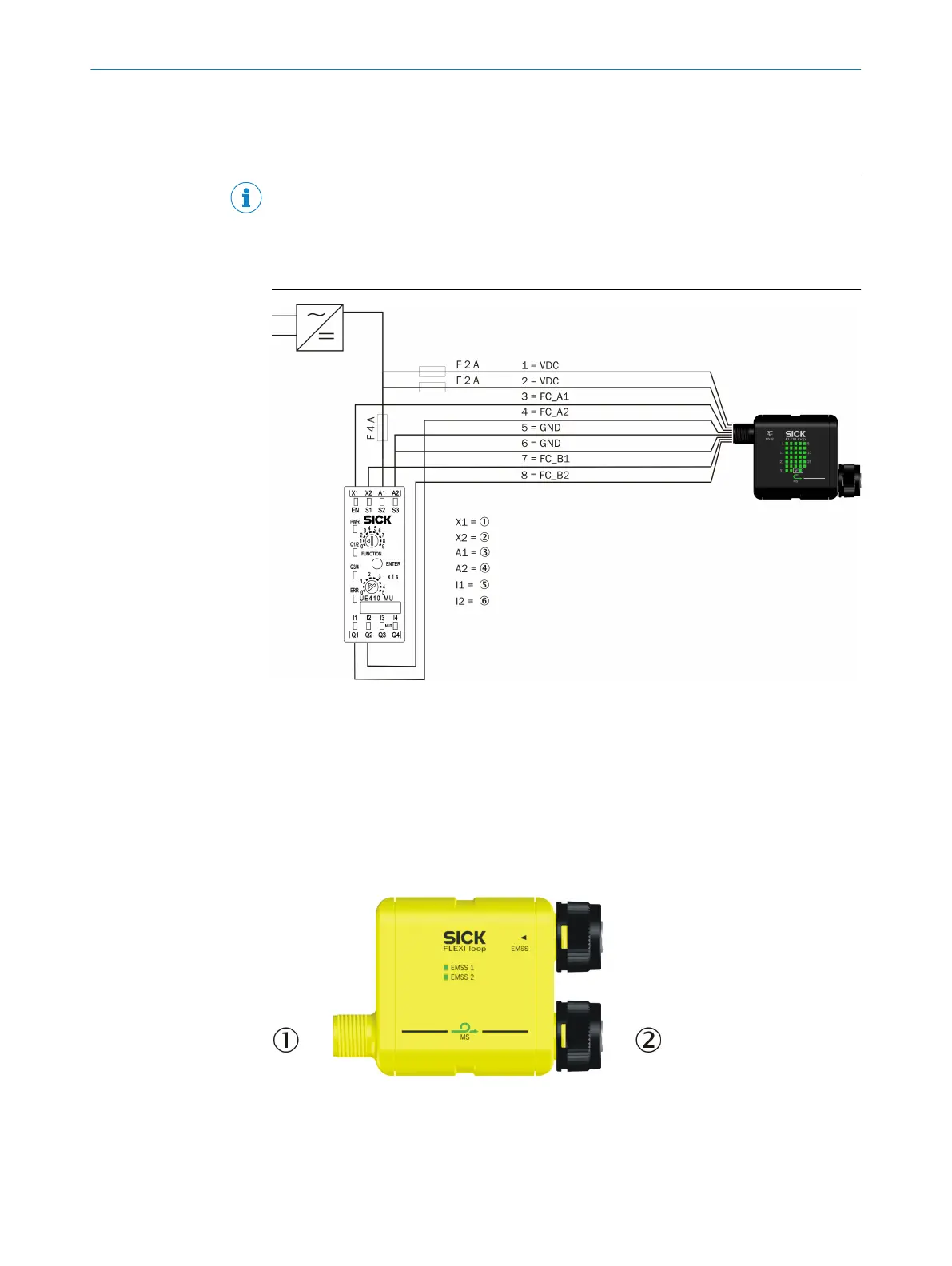
Connect the Flexi Loop MSTR accessory to two outputs (X) and two safe inputs (I) of the
saf
ety controller. Use 8-pin cables with M12 female connector and open cable ends to
connect the safe sensor cascade (see "Pre-assembled cables", page 95).
NOTE
If y
ou connect the safe sensor cascade to the same power supply as the safety control‐
ler, then limit the current to 4 A.
Use both power supply pins (1 and 2) and both GND pins (5 and 6) on the MSTR Flexi
Loop accessory for the power supply.
Figure 43: Connection to Flexi Classic
1
FC_A1
2
FC_B1
3
VDC
4
GND
5
FC_A2
6
FC_B2
6.2.3 Connections of the Flexi Loop nodes
Figure 44: Connections of the Flexi Loop nodes
1
FL_IN (male connector)
2
FL_OUT (female connector)
6 ELECTRICAL INSTALLATION
44
O P E R A T I N G I N S T R U C T I O N S | Flexi Loop 8015836/YT10/2016-05-24 | SICK
Subject to change without notice