PWR Right Meaning
Gr
een
Input voltage on the right side (on the male connector PWRI) is in the
s
tipulated range
No or excessively low input voltage on the right side (on the male con‐
nector PWRI)
Table 36: PWR Right LED of the PWRI power supply accessory
PWR Left Meaning
Gr
een
Operating voltage in the left section in the stipulated range
No or excessively low operating voltage in the left section
Table 37: PWR Left LED of the PWRI power supply accessory
Overload Meaning
Output current in the normal range
R
ed (1 Hz)
Output load is critical but not yet cut off. If this continues, cut-off will
occur (see "PWRI po
wer supply accessory", page 85).
R
ed
Overload, all sections to the right of the power supply accessory are
shut do
wn. If the load drops below the re-enable value, the power sup‐
ply accessory switches back on.
R
ed (2 Hz)
Emergency shutdown, this error can only be cleared by switching off
and on ag
ain.
Table 38: Overload LED of the PWRI power supply accessory
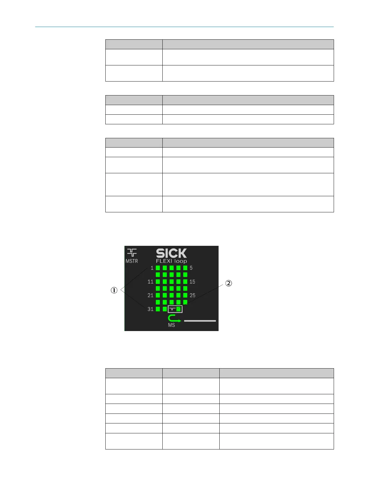
9.3.5 LEDs of the MSTR1 Flexi Loop accessory
Figure 64: LEDs of the MSTR1 Flexi Loop accessory
1
Node LEDs 1 to 32
2
Operating mode LED
Node LEDs 1 to 32 MS LED Meaning
–
Node not found (not connected, not in opera‐
tion)
Gr
een
–
OSSD or EMSS in the ON state
Gr
een
–
OSSD or EMSS in the OFF state
R
ed
–
Sequence error occurred on the node
R
ed
– Discrepancy error occurred on the node
Gr
een (2 Hz) Red/green (2 Hz)
Node found, corresponds to expected configu‐
r
ation
Table 39: Node LEDs of the MSTR1 and MSTR2 Flexi Loop accessory
TROUBLESHOOTING 9
8015836/YT10/2016-05-24 | SICK O P E R A T I N G I N S T R U C T I O N S | Flexi Loop
73
Subject to change without notice