4 Design
The safe sensor cascade makes it possible to cover a large distance. On the other hand
a lar
ge number of switches, sensors, actuators and LEDs can be connected.
Due to the cable lengths and the power consumption, it is imperative you pay attention
to two things:
•
The total current in the safe sensor cascade must not exceed 4 A at any point!
3)
•
The voltage VDC must be present at each input on a Flexi Loop node in the range
from 16.8 … 30 V DC!
4.1 Total current
DANGER
The t
otal current within a section of the safe sensor cascade must be limited to 4 A!
The safe sensor cascade permits a maximum total current of 4 A. Use a suitable protec‐
tion device or current limiters so that the input current does not exceed 4 A.
The magnitude of the total current is dependent on the following factors:
•
number of nodes
•
cur
rent consumption of the sensors and actuators connected
4.1.1 Permissible total current of a section
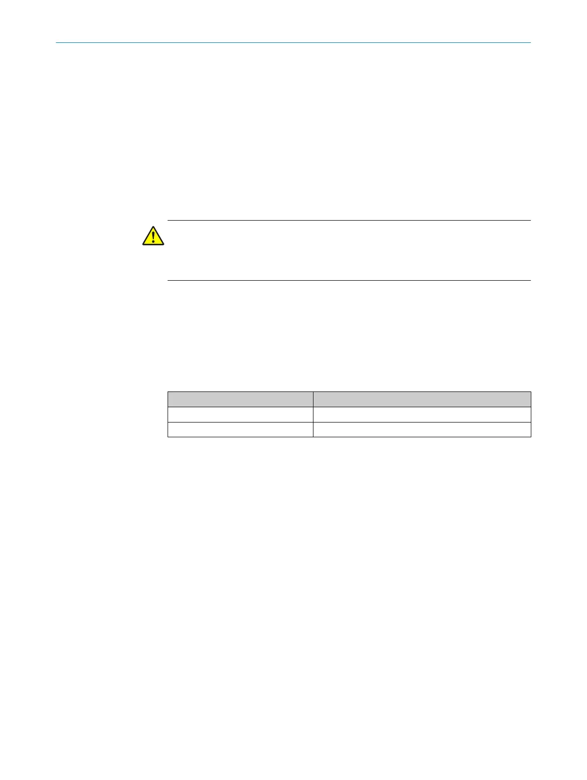
The permissible total current within a section is dependent upon the ambient tempera‐
tur
e (see "Division into sections", page 30).
Ambient temperature Permissible total current
1)
40 °C 4.0 A
55 °C 3.19 A
Table 3: Permissible total current within a section
1)
At UL/CSA applications only 3.2 A.
4.1.2 Permissible inrush current
Limit the inrush current flowing through the PWRI connection of the PWRI power supply
accessor
y to less than 40 A. Failure to do this may cause the short-circuit limiter associ‐
ated with the power supply accessory to trip.
Possible solutions:
•
Use a suitable current-limited power supply unit.
•
Increase the electrical resistance between the power supply unit and the first Flexi
Loop node downstream of the PWRI power supply accessory to 0.75 Ω (e.g., by
reducing the wire cross-section or increasing the length of the cable).
Tip: Minimum length of the cable between power supply unit and Flexi Loop node
= wire cross-section × 25 m/mm
2
(e.g., 8.5 m for 0.34 mm
2
).
4.1.3 Other limits
It is possible to connect sensors with a maximum current consumption of 3.9 A to the
OSSD de
vice connection on the FLN-OSSD1000105 Flexi Loop node.
A maximum current of 2 A is allowed to flow through the 8-pin M12 female connectors
on the Flexi Loop nodes (AUX_OUT + VDC).
4)
3)
A
t an ambient temperature of 40 °C.
DESIGN 4
8015836/YT10/2016-05-24 | SICK O P E R A T I N G I N S T R U C T I O N S | Flexi Loop
27
Subject to change without notice